|
Circuit Breaker - Working Principle
A circuit breaker operates by monitoring electrical current, using an internal switch to automatically interrupt flow during overloads or short circuits. It uses magnetic (for fast, high-current faults) or thermal (for slower overloads) tripping mechanisms to separate fixed and moving contacts, extinguishing the resulting electric arc to prevent damage.
Key working principles include
- Normal Condition: Contacts are closed, allowing current to pass. The mechanism holds these together with spring or mechanical pressure.
- Fault Detection (Overload): A bimetallic strip heats up and bends, triggering the tripping mechanism.Fault
- Detection (Short Circuit): Excessive current creates a strong magnetic field in an electromagnet, which instantly pulls a lever to trip the mechanism
- Arc Extinction Process: As contacts separate, a plasma arc forms. The breaker extinguishes this arc by breaking it into smaller pieces, cooling it, or using insulating gases (SF6) to increase dielectric strength between the contacts
- Arc Stretching: The arc is mechanically stretched using arc runners and magnetic fields, increasing its length and resistance.
- Arc Cooling: Compressed air or natural convection cools the arc plasma, reducing its conductivity.
- Arc Splitting: Arc chutes with metal plates divide the arc into multiple smaller arcs, dramatically increasing the total arc voltage.
- High-Resistance Path Creation: The combined effect of stretching, cooling, and splitting creates a high-resistance path that exceeds the system’s ability to maintain the arc.
- Resetting: Once the fault is cleared, the device can be reset manually or automatically to restore power.
Common types include Miniature Circuit Breakers (MCB) for homes, molded case breakers, and high-voltage SF6 or air circuit breakers.
Core Working Principle
| Protection Type |
Trigger Cause |
Mechanism |
Action |
| Thermal Protection |
Overload (Gradual excess current) |
Bimetallic Strip: Two metals with different expansion rates bend when heated by high current. |
The bending strip physically trips a latch, opening the contacts. |
| Magnetic Protection |
Short Circuit (Sudden massive spike) |
Electromagnet/Solenoid: A sudden surge creates a powerful magnetic field instantly. |
The magnetic force pulls a plunger or armature to trip the latch immediately. |
The "Trip" Process
- Fault Detection: Internal sensors (bimetallic strip for heat or a coil for magnetism) detect current exceeding the breaker's rated limit.
- Mechanical Separation: The detection mechanism releases a spring-loaded latch. This stored energy rapidly pulls the moving contact away from the fixed contact.
- Arc Quenching: As contacts separate, electricity jumps the gap, creating a high-heat arc. The breaker must quickly extinguish this arc using an Arc Chute (which splits and cools the arc) or insulating mediums like air, oil, vacuum, or SF6 gas to prevent damage.
- Reset: Once the fault is cleared, the breaker can be manually switched back to the "ON" position.
Common Types of Circuit Breakers
Contact Design
Most ACBs feature a dual-contact system:
- Main Contacts: Made of copper, carry normal load current
- Arcing Contacts: Made of carbon or special alloys, handle the arc during switching operations
For more details see figure below
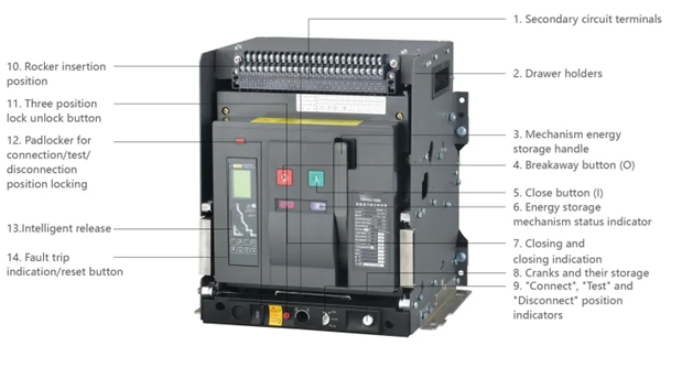
Primary Structural Elements
- Contact System:
- Main Contacts: Arc-resistant copper contacts that effectively protect against erosion during short-circuit current breaking
- Arcing Contacts: Specialized contact material designed to withstand high temperatures without overheating
- Contact Pressure System: Multiple contact connections in parallel reduce electric repulsion and improve stability
- Arc Extinguishing System
- Arc Suppressing Chamber: Insulated chamber housing that increases mechanical strength and prevents external interference
- Arc Chutes: Structured chambers with insulating barriers that cool, stretch, and divide arcs into smaller segments
- Arc Runners: Guide the arc away from main contacts into the extinguishing chamber
- Protection and Control Systems:
- Drawer-Type Mechanism (where applicable):
Types of Air Circuit Breakers
Understanding the different types of air circuit breaker helps in selecting the right device for specific applications:
- Plain Break (Cross-Blast) Air Circuit Breakers
- Magnetic Blowout Air Circuit Breakers
- Construction: Incorporates electromagnetic coils (blowout coils) connected in series with the main circuit.
- Working Mechanism: The magnetic field generated by fault current helps deflect and stretch the arc into arc chutes.
- Applications: Medium-voltage applications where faster arc extinction is required.
- Air Chute Air Circuit Breakers
- Construction: Features specially designed arc chutes with metal splitter plates and insulating barriers.
- Arc Extinction Method: The arc is guided into chutes where it’s cooled, lengthened, and split into multiple series arcs.
- Applications: Industrial plants, commercial buildings, and power distribution systems.
- Excellent arc extinction capability
- Suitable for frequent operations
- Lower maintenance requirements
- Air Blast Circuit Breakers
- Construction: Uses high-pressure compressed air systems to forcibly extinguish arcs.
- Working Principle: Compressed air (typically 20-30 bar pressure) creates a powerful blast that rapidly cools and extinguishes the arc.
- Applications: High-voltage applications up to 15kV and critical installations requiring rapid fault clearing.
Features:
- Fastest arc extinction method
- Suitable for high-fault current applications
- Requires air compressor systems
Advanced Protection and Control Systems
Modern ACBs incorporate sophisticated microprocessor-based controllers that provide:
- Protection Functions:
- Overcurrent Protection: Adjustable time-current characteristics for optimal coordination
- Short-Circuit Protection: Instantaneous trip for high-fault currents
- Ground Fault Protection: Sensitive detection of earth leakage currents
- Undervoltage Protection: Configurable voltage monitoring with time delays
- Phase Loss Protection: Detection of single-phase conditions in three-phase systems
- Monitoring and Measurement:
- Current Measurement: Real-time monitoring of all three phases
- Voltage Monitoring: Continuous voltage level assessment
- Power Quality Analysis: Harmonic analysis and power factor monitoring
- Energy Metering: Accurate measurement of energy consumption
- Communication Capabilities:
- Digital Communication Interfaces: Modbus, Profibus, or Ethernet connectivity
- Remote Monitoring: Integration with SCADA and building management systems
- Data Logging: Historical data storage for analysis and trending
- Alarm Generation: Configurable alarms for various operating conditions
Electronic Trip Units
Electronic trip units offer significant advantages over traditional thermal-magnetic protection:
- Adjustable Settings: Fine-tuning of protection parameters for optimal coordination
- Multiple Protection Curves: Various time-current characteristics for different applications
- Zone Selective Interlocking: Coordination with upstream and downstream devices
- Arc Flash Reduction: Specialized settings to minimize arc flash energy
Advanced Features:
- Load Profiling: Analysis of load patterns for predictive maintenance
- Fault Recording: Detailed fault analysis with waveform capture
- Self-Diagnostics: Continuous monitoring of protection system health
- Password Protection: Secure access to critical settings
Auxiliary Contacts and Accessories
- Configuration Options: Available in various contact combinations (NO/NC)
- Electrical Ratings:
- AC Applications: 230V/400V, up to 6A
- DC Applications: 110V/220V, up to 6A
- Mechanical Life: Up to 300,000 operations
- Applications: Position indication, alarm signaling, interlocking circuits
- Closing/Opening Coils: Remote electrical operation capability
- Undervoltage Releases: Automatic tripping on voltage loss
- Shunt Releases: Emergency remote tripping functionality
- Motor Operating Mechanisms: Automatic spring charging systems
- Communication Modules: Integration with digital control systems
ACB vs Other Circuit Breaker Types
| Feature |
Air Circuit Breaker |
Oil Circuit Breaker |
| Arc Medium |
Air/Compressed Air |
Mineral Oil |
| Fire Risk |
Minimal |
High risk due to oil |
| Maintenance |
Lower |
Higher (oil changes required) |
| Environmental Impact |
Eco-friendly |
Oil disposal concerns |
| Installation |
Simpler |
Requires oil handling systems |
| Cost |
Moderate |
Lower initial cost |
Air Circuit Breaker vs SF6 Circuit Breaker
| Feature |
Air Circuit Breaker |
SF6 Circuit Breaker |
| Arc Medium |
Air |
Sulfur Hexafluoride Gas |
| Voltage Range |
Up to 15kV typically |
Higher voltage applications |
| Environmental |
Zero environmental impact |
SF6 is a greenhouse gas |
| Maintenance |
Standard procedures |
Requires gas handling expertise |
| Size |
Larger footprint |
More compact |
| Cost |
Lower |
Higher |
Air Circuit Breaker vs Vacuum Circuit Breaker
| Feature |
Air Circuit Breaker |
Vacuum Circuit Breaker |
| Arc Medium |
Air |
Vacuum |
| Voltage Range |
Low to medium voltage |
Medium voltage preferred |
| Maintenance |
Regular contact inspection |
Minimal maintenance |
| Life Expectancy |
10,000-20,000 operations |
30,000+ operations |
| Size |
Larger |
More compact |
| Applications |
Industrial/Commercial |
Power distribution |
Installation Guide and Safety Procedures
Pre-Installation Requirements - Environmental Conditions
Temperature Requirements:
- Operating Range: -5°C to +40°C ambient temperature
- Average Daily Temperature: Maximum +35°C (24-hour average)
- Storage Temperature: Extended range for non-operating conditions
Humidity Specifications:
- Maximum Relative Humidity: 50% at +40°C maximum temperature
- Condensation Prevention: Higher humidity acceptable at lower temperatures
- Monthly Averages: Specific limits for wettest months to prevent moisture-related issues
Installation Site Requirements:
- Maximum Altitude: 2000m above sea level without derating
- Pollution Level: Category B protection level for standard applications
- Vibration Limits: Mechanical stability requirements per IEC standards
- Mounting Orientation: Maximum 5° inclination from vertical position
Power Supply and Control Requirements
Main Circuit Specifications:
- Voltage Ratings: Typically 400V/690V AC systems
- Frequency: 50Hz/60Hz operation
- Installation Categories: Category IV for main circuits, Category III for auxiliary circuits
Auxiliary Power Systems:
- Control Voltage: Multiple options (24V, 110V, 230V DC/AC)
- Power Consumption: Optimized for minimal standby power
- Backup Systems: Battery backup capability for critical applications
ACB Model Designation and Selection
Understanding ACB Model Codes
Air circuit breaker model designations follow standardized naming conventions that indicate key specifications:
Typical Model Code Structure:
- Enterprise/Brand Code: Manufacturer identification
- Universal Designation: Indicates ACB type (e.g., “W” for universal circuit breaker)
- Design Generation: Version or design iteration number
- Frame Size: Indicates maximum current capacity (e.g., 1600A, 3200A, 6300A)
- Pole Configuration: Number of poles (3-pole standard, 4-pole available)
Frame Class Ratings:
- 800A Frame: Suitable for medium-scale industrial applications
- 1600A Frame: Common for large motor control and distribution centers
- 3200A Frame: Heavy industrial and utility applications
- 6300A Frame: Main distribution and utility substation applications
Technical Parameter Specifications
Breaking Capacity Ratings:
- Ultimate Short-Circuit Breaking Capacity (Icu): Maximum fault current the breaker can interrupt
- Operating Short-Circuit Breaking Capacity (Ics): Service breaking capacity (typically 75% of Icu)
- Short-Circuit Making Capacity: Peak current the breaker can close against
Electrical Life Ratings:
- Mechanical Life: Number of no-load operations (typically 10,000-25,000)
- Electrical Life: Number of operations under rated load
- Maintenance Intervals: Recommended service periods based on operation count
Step-by-Step Air Circuit Breaker Installation
Safety Procedures
CRITICAL: Always follow lockout/tagout procedures before beginning installation.
- De-energize the system and verify zero energy state using appropriate testing equipment
- Install safety barriers and warning signs in the work area
- Use proper PPE: Insulated gloves, safety glasses, arc-rated clothing, and hard hats
- Ensure proper grounding of all equipment during installation
Mechanical Installation
Step 1: Foundation Preparation
- Ensure the mounting surface is level, rigid, and capable of supporting the ACB weight
- Install vibration dampening materials if required
- Verify adequate clearances per manufacturer specifications
Step 2: ACB Mounting
- Use appropriate lifting equipment for heavy units
- Align the ACB with mounting points
- Secure using manufacturer-specified bolts with proper torque values
- Install seismic restraints if required by local codes
Step 3: Electrical Connections
- Connect incoming and outgoing conductors to designated terminals
- Apply manufacturer-recommended torque values to all connections
- Use proper cable lugs and connection hardware
- Ensure phase rotation and proper grounding connections
Control and Protection Wiring
Protection Relay Connections:
- Connect current transformers (CTs) with proper polarity
- Wire voltage transformers (VTs) if required
- Install auxiliary contacts for indication and control
Control Circuit Wiring:
- Connect closing and opening coils
- Wire auxiliary power supplies
- Install interlocking circuits as required
- Test all control functions before energization
Testing and Commissioning
Visual Inspection Checklist:
- Verify all connections are tight and properly labeled
- Check for foreign objects or debris
- Confirm proper contact alignment
- Verify protection settings match design requirements
Electrical Testing:
- Insulation resistance testing of all circuits
- Contact resistance measurement
- Trip unit calibration and testing
- Control circuit functionality verification
- Operational testing under no-load conditions
Maintenance Best Practices
Preventive Maintenance Schedule - Monthly Inspections
Visual Checks:
- Inspect for signs of overheating (discoloration, burning odors)
- Check for loose connections or damaged components
- Verify control panel indicators function properly
- Examine arc chutes for damage or contamination
Operational Verification:
- Test manual operation mechanisms
- Verify trip indicator functions
- Check auxiliary contact operation
- Monitor protection relay displays
Quarterly Maintenance
Contact Inspection:
- Measure main contact resistance
- Check contact alignment and wear
- Inspect arcing contacts for erosion
- Verify proper contact wipe and pressure
Mechanical Components:
- Lubricate operating mechanisms per manufacturer instructions
- Check spring tension and energy storage systems
- Inspect linkages for wear or misalignment
- Verify proper closing and opening times
Annual Comprehensive Maintenance
Electrical Testing:
- Perform insulation resistance tests on all circuits
- Conduct high-potential (hi-pot) testing
- Test protection relay accuracy and timing
- Verify current transformer accuracy
Mechanical Overhaul:
- Disassemble and inspect operating mechanisms
- Replace worn components and consumables
- Calibrate torque settings on all connections
- Update lubrication throughout the system
Critical Maintenance Procedures
Contact Replacement Guidelines:
- Replace main contacts when resistance exceeds manufacturer limits
- Replace arcing contacts when erosion reaches minimum thickness
- Ensure proper contact material specifications
- Follow manufacturer assembly procedures exactly
Arc Chute Maintenance:
- Clean insulating plates with approved solvents
- Check for cracks or carbon tracking
- Replace damaged components immediately
- Verify proper assembly and alignment
Maintenance Documentation
Record Keeping Requirements:
- Maintain detailed logs of all inspections and tests
- Document any abnormal findings or corrective actions
- Track component replacement history
- Keep manufacturer manuals and technical documentation current
Performance Trending:
- Monitor contact resistance trends over time
- Track trip unit operation history
- Document environmental conditions during service
- Analyze failure patterns for predictive maintenance
Troubleshooting Common Issues
ACB Will Not Close- Possible Causes and Solutions
Undervoltage Release Issues:
- Symptom: Breaker trips immediately after closing attempt
- Diagnosis: Check control voltage levels and connections
- Solution: Verify rated voltage supply to undervoltage release coil; repair any loose connections or blown fuses
Spring Energy Storage Problems:
- Symptom: Closing mechanism lacks sufficient force
- Diagnosis: Check spring charging motor operation and spring tension
- Solution: Replace energy storage springs or repair charging motor; verify proper spring compression
Mechanical Binding:
- Symptom: Sluggish or incomplete closing operation
- Diagnosis: Inspect operating mechanism for foreign objects or insufficient lubrication
- Solution: Clean mechanism thoroughly; apply proper lubricants; remove any foreign materials
Control Circuit Failures:
- Symptom: No response to closing commands
- Diagnosis: Test control circuit continuity and component function
- Solution: Repair broken wiring; replace faulty relays or control switches; verify auxiliary contact operation
Unwanted Tripping (Nuisance Trips)
Protection System Issues
Overcurrent Settings:
- Problem: Trip settings too sensitive for actual load conditions
- Diagnosis: Compare actual load current with trip settings
- Solution: Adjust protection settings within safe parameters; coordinate with system study
Current Transformer Problems:
- Problem: CT burden too high or connections loose
- Diagnosis: Check CT secondary circuit integrity and burden calculations
- Solution: Reduce CT burden; tighten all connections; verify CT ratio accuracy
Environmental Factors:
- Problem: Temperature, humidity, or vibration affecting operation
- Diagnosis: Monitor environmental conditions during operation
- Solution: Improve ventilation; install vibration dampening; relocate if necessary
Contact Problems (Contact Overheating)
Loose Connections:
- Diagnosis: Use infrared thermography to identify hot spots
- Solution: Re-torque all connections to specification; replace damaged hardware
Contact Deterioration:
- Diagnosis: Measure contact resistance and compare to baseline values
- Solution: Clean or replace contacts as needed; investigate cause of excessive wear
Arcing Issues
Arc Chute Problems:
- Diagnosis: Inspect for carbon buildup or damaged insulating plates
- Solution: Clean or replace arc chute components; verify proper assembly
Contact Alignment:
- Diagnosis: Check contact mating surfaces and alignment
- Solution: Adjust contact position; replace worn components; verify proper wipe action
Electronic Trip Unit Failures
Digital Display Issues
- Problem: Blank or incorrect displays
- Solution: Check power supply; update firmware; replace defective unit
Communication Failures
- Problem: Loss of remote monitoring capability
- Solution: Verify communication cables; check protocol settings; test network connectivity
Applications and Use Cases
Manufacturing Plants:
Power Distribution Centers: ACBs serve as main breakers in low-voltage motor control centers, protecting multiple motor circuits and distribution feeders.
Heavy Machinery Protection: Large industrial equipment like steel mills, mining operations, and chemical processing plants rely on ACBs for reliable overcurrent protection.
Case Study: A steel manufacturing facility uses 4000A ACBs to protect their electric arc furnace feeders, providing reliable protection while minimizing downtime during maintenance operations.
Power Generation Facilities:
Generator Protection: ACBs protect generators from reverse power, overcurrent, and short-circuit conditions in power plants.
Auxiliary Power Systems: Essential for protecting power plant auxiliary systems including cooling pumps, ventilation systems, and control power supplies.
Power Generation Facilities
International Standards
IEC Standards:
- IEC 61439: Low-voltage switchgear and control assemblies – defines performance requirements for ACB installations.
- IEC 62271: High-voltage switchgear and control assemblies – covers medium-voltage ACB applications.
- IEC 60947: Low-voltage switchgear and control gear – specifies ACB performance characteristics and testing requirements.
IEEE Standards
- IEEE C37.04: Standard rating structure for AC high-voltage circuit breakers.
- IEEE C37.09: Standard test procedures for AC high-voltage circuit breakers.
- IEEE C37.06: Standard for AC high-voltage circuit breakers rated on a symmetrical current basis.
National and Regional Codes
United States
- National Electrical Code (NEC): Article 240 covers overcurrent protection requirements and ACB applications.
- UL 489: Standard for molded-case circuit breakers and circuit-breaker enclosures.
- NEMA Standards: Various standards covering ACB performance, testing, and application guidelines.
European Union
- EN 61439: European standard for low-voltage switchgear assemblies.
- EN 62271: High-voltage switchgear standards.
- CE Marking Requirements: Mandatory conformity marking for ACBs sold in EU markets.
Safety and Environmental Regulations
Workplace Safety
- OSHA Standards: 29 CFR 1910 Subpart S covers electrical safety requirements for ACB installation and maintenance.
- NFPA 70E: Standard for electrical safety in the workplace, including ACB maintenance procedures.
Environmental Compliance
- RoHS Directive: Restriction of hazardous substances in electrical equipment.
- WEEE Directive: Waste electrical and electronic equipment disposal requirements.
- ISO 14001: Environmental management system standards for ACB manufacturing and disposal.
|


