Current Transformers (CTs) in circuit breakers - Working Principle

current transformer2a current transformer1a


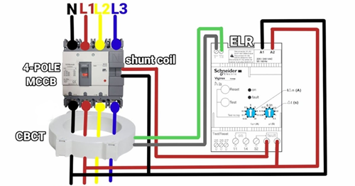
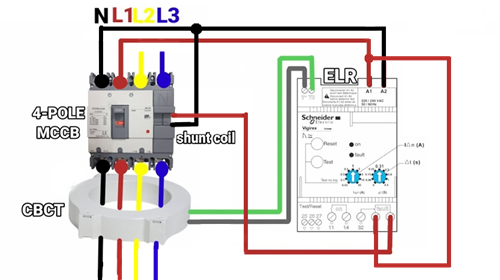
Current Transformers (CTs) in circuit breakers work on the principle of electromagnetic induction. They step down high-magnitude line currents (primary) to a low, safe, and measurable standard (1A or 5A secondary). A magnetic core, connected in series, transforms the current proportionally based on a fixed turns ratio to drive protection relays.

Key Aspects of CT Operation in Circuit Breakers:
  • Working Principle: Primary current induces a magnetic field in the core, creating a proportionate current in the secondary winding.
  • Circuit Connection: The primary winding (often just the conductor passing through the core) is in series with the high-voltage circuit, while the secondary connects to meters or relays.
  • Turns Ratio: A higher number of secondary turns reduces the current proportionally, with formula N1 I1 = N2 I2.
  • Safety Warning: A CT secondary should never be open-circuited while the primary is energized, as this can produce dangerously high voltages.
  • Protection Function: When faults occur (high current), the CT senses the surge and triggers the circuit breaker to trip, isolating the system.

In a circuit breaker system, a Current Transformer (CT) acts as the "eyes" of the protective relay, accurately scaling down high primary currents to a safe, manageable level (typically 1A or 5A) for monitoring and tripping.

Working Principle

A CT operates on the principle of Electromagnetic Induction (Faraday’s Law).

Step Process Description
1. Primary Flow The high alternating current (AC) of the main circuit flows through the primary winding (often just the main conductor passing through the CT core).
2. Magnetic Flux This primary current generates a proportional magnetic field in the transformer's magnetic core.
3. Secondary Induction The changing magnetic flux in the core induces a voltage and current in the secondary winding, which has many more turns of wire than the primary.
4. Current Scaling The output current is inversely proportional to the turns ratio. For example, a 1000:5 ratio CT reduces a 1000A primary current to a 5A secondary signal.
5. Relay Activation This 5A signal is fed into a protective relay. If the signal exceeds a set threshold (indicating a fault), the relay triggers the circuit breaker to open and isolate the fault.


Key Component Roles

  • Magnetic Core: Concentrates the magnetic flux to ensure high-fidelity signal transfer without energy loss.
  • Secondary Winding: Provides the scaled-down current and maintains electrical isolation between the high-voltage line and sensitive control equipment.
  • Protective Relay Integration: The CT continuously sends real-time data to the relay, which evaluates the system status in milliseconds.
Critical Safety Warning
Never leave a CT’s secondary circuit open while current is flowing in the primary. Without a closed secondary loop, the primary magnetic force is unopposed, causing the magnetic flux to skyrocket. This can induce dangerously high voltage spikes (thousands of volts), leading to insulation failure or fatal electric shock.
Provide the [System Voltage Level] and [Desired Protection Type] (e.g., Overcurrent or Differential) to determine the specific CT accuracy class required for your application.

favicon bacd

+(39) 347 051 5328

Italy - Kazakhstan

09.00am to 18.00pm

About

We offer the best and economical solutions, backed by 27+ years of experience and international standards knowledge, echnological changes, and industrial systems.

Marketing Materials

Spring Renovation
Industry
US Gas Company
Construct
Plus Project
Vam Drilling Service
X Project
X Project
Cabrrus Training

Marketing Materials1

Spring Renovation
Industry
US Gas Company
Construct
Plus Project
Vam Drilling Service
ultrasonic sensor
ultrasonic sensor
Cabrrus Training