|
Drawer Base of a circuit breaker - Working Principle
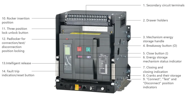
A drawer base (or cradle/chassis) for a draw-out circuit breaker provides a secure, sliding mounting mechanism that allows the breaker to be safely racked in or out for maintenance without disconnecting main wiring. It acts as a stationary docking station, connecting the breaker to main power circuits through stab-in connectors at three distinct positions: Connected, Test, and Disconnected.
Working Principle and Key Features
- Mechanical Support & Sliding: The circuit breaker rests on a, typically, steel structure containing rails. These allow the breaker to slide in and out of the cubicle, with lockable positions for safety.
- Stab-In Connections: As the breaker is inserted (racked in), fixed, female-type connections on the base mate with the male-type primary contacts on the breaker. This establishes the main high-voltage circuit.
- Primary Positions:
- Connected: Main circuit is closed, auxiliary circuits are connected.
- Test: Main circuit is disconnected, but auxiliary circuits remain connected, allowing for testing of the operating mechanism.
- Disconnected/Withdraw: Both main and auxiliary circuits are separated from the breaker, making it completely isolated and safe for maintenance.
- Safety Interlocks: The base often includes shutter systems that cover the live, fixed primary contacts when the breaker is removed, preventing accidental contact.
- Safety Features: The design facilitates rapid replacement to minimize downtime, while the "Draw-out" feature ensures the operator is not exposed to live components during maintenance.
The drawer base (also known as a fixed cradle or cassette base) of a draw-out circuit breaker acts as the permanent interface between the electrical switchboard and the removable breaker unit. Its primary principle is to allow for safe "racking" of the breaker into different operational states without de-energizing the entire panel.
Working Principle & Racking Positions
The base uses a mechanical racking mechanism (typically a hand crank or screw rod) to move the breaker between three distinct positions:
| Position |
Electrical Connection Status |
Purpose |
| Connected |
Both main (power) and auxiliary (control) circuits are engaged. |
Normal operation; power flows through the breaker to the load. |
| Test |
Main power contacts are disconnected; auxiliary control circuits remain connected. |
Allows testing of the breaker's internal logic and trip units without a live load. |
| Disconnected |
Both main and auxiliary circuits are fully separated. |
Complete physical isolation for safe removal or maintenance. |
Key Components and Safety Mechanisms
- Main Bus Connectors: Permanent stabs at the back of the base that connect to the switchboard's vertical bus bars.
- Automatic Shutters: Safety barriers that slide closed when the breaker is withdrawn to prevent accidental contact with live bus bars.
- Mechanical Interlocks: Safety "locks" that prevent the breaker from being racked in or out while the contacts are closed (energized), avoiding dangerous arc flashes.
- Secondary Wiring Device: A pull-apart terminal block that connects breaker accessories (like trip alarms or remote signals) to the external system.
For detailed installation or maintenance procedures, refer to technical guides from manufacturers like Eaton or ABB.
|


