|
Position Indicators of a circuit breaker - Working Principle
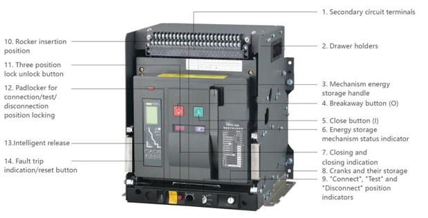
Circuit breaker position indicators are mechanical or electrical devices (flags/LEDs) that provide immediate, visual status of a circuit breaker’s main contacts (Open, Closed, or Tripped) and the operating mechanism's energy state (Charged or Discharged). They ensure safety by indicating if power is connected or disconnected.
Key Position Indicators and Working Principles
- Contact Position Indicator (Open/Closed/Tripped):
- Principle: Linked directly to the operating mechanism (movable contacts). When the breaker opens or closes, the mechanical linkage moves a pointer/flag (e.g., Red for Closed/On, Green/White for Open/Off).
- Tripped: A middle position indicator or a separate red trip flag shows the breaker has tripped and must be reset.
- Spring Mechanism Indicator (Charged/Discharged):
- Principle: Indicates the status of the closing spring (used to store energy for closing contacts).
- Charged (Ready): The spring is compressed; the indicator often shows a yellow/white symbol (e.g., "charged" or "closed"), indicating it can safely close the circuit.
- Discharged: The spring has released energy; the indicator shows "discharged" (or open), meaning the breaker cannot close until recharged.
- Racking/Connection Position (For Drawout/MV Breakers):
- Principle: Indicates if the breaker is Connected (fully engaged), Test (disconnected from power, connected for control testing), or Disconnected (fully separated).
These indicators are crucial for maintenance, preventing "blind" operation of high-voltage equipment, and ensuring the stored energy is available for safe, rapid switching.
Circuit breaker position indicators provide real-time status of the device's internal contacts—ON (closed), OFF (open), or TRIPPED. Their primary working principle relies on a mechanical linkage connected to the breaker's operating shaft; as the contacts move, they physically shift a flag, handle, or auxiliary switch to reflect the new state.
Types of Position Indicators
| Indicator Type |
Working Principle |
Typical Use |
| Visual (Mechanical) |
A physical flag or the handle itself moves to a specific position (e.g., midway for "Tripped"). |
Residential panels & manual breakers. |
| Auxiliary Contacts |
Secondary switches mechanically linked to the main shaft. They open/close to send electrical signals to remote systems. |
Industrial control, SCADA, & alarms. |
| Electronic/Digital |
Sensors (like Hall-effect or magnetic) detect the shaft's position and display status on a screen or LED. |
Smart breakers & advanced switchgear. |
| Spring Status |
Shows if the closing spring is "Charged" or "Discharged," indicating if the breaker is ready to close. |
High-voltage / Draw-out breakers. |
Core Working Principles
- Mechanical Synchronization: The indicator is physically tied to the moving contact assembly. This ensures the status shown is accurate even if there is no electrical power to the indicator itself (in mechanical versions).
- Trip-Free Mechanism: In a "Tripped" state, the indicator handle often moves to a center position, distinct from manual "OFF". This is triggered by the internal Trip Unit (thermal or magnetic) releasing the latch independently of the external handle.
- Contact Signaling: Auxiliary switches use "a" contacts (which mirror the main contact's state) and "b" contacts (which show the opposite state) to provide flexible logic for remote monitoring.
For high-voltage systems, indicators also track the Racking Position (Connected, Test, or Disconnected) to ensure safety during maintenance.
|


