|
Modbus operates on a master-slave
Modbus operates on a master-slave (or client-server) principle where a single master device (e.g., PLC, SCADA) initiates requests to one or more slave devices (e.g., sensors, actuators). The master requests data or sends commands via specific addresses, and slaves respond to these requests, typically over serial (RS-485/232) or Ethernet (TCP/IP) lines.
Key Aspects of Modbus Working Principle
- Master-Slave Structure: Only the master can initiate communication. Slaves cannot initiate conversations, they only respond to inquiries directed to them.
- Request-Reply Mechanism: The master sends a frame (address, function code, data, CRC). The addressed slave processes the request and sends a response.
Addressing: Each slave has a unique address (1-247). A slave only responds if it recognizes its address.
- Data Types: Data is organized into four main types: Coils (read/write bits), Discrete Inputs (read-only bits), Holding Registers (read/write 16-bit values), and Input Registers (read-only 16-bit values).
- Function Codes: Defined in the message, these codes instruct the slave to perform specific actions (e.g., Read Holding Register = 03, Write Coil = 05).
Error Checking: Modbus RTU uses a CRC (Cyclic Redundancy Check) to ensure data integrity.
Variations
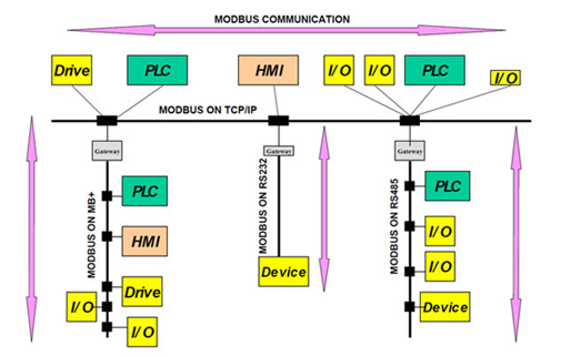
- Modbus RTU: Binary transmission for high speed, usually over RS-485.
- Modbus TCP/IP: Uses Ethernet for communication, wrapping the frame in a TCP packet, eliminating the need for checksums.
- Modbus ASCII: Uses ASCII characters for communication, suitable for modems.
Common Use Case
An HMI (Master) requests the temperature value from a sensor (Slave) by sending a request to read a specific holding register. The sensor sends back the data, which the HMI then displays.
Modbus is an open-source, messaging-layer protocol that facilitates communication between automation devices. Developed in 1979 by Modicon (now Schneider Electric), it has become a de facto standard in industrial environments for its simplicity and reliability.
Core Working Principle
Modbus operates on a Request-Response model, typically utilizing a Master-Slave (or Client-Server) architecture:
Master (Client): The initiating device (e.g., a PLC or SCADA system) that sends a query to a specific slave.
Slave (Server): The responding device (e.g., a sensor or actuator) that processes the request and sends back a response. Slaves cannot initiate communication on their own.
Data Model and Registers
Data is organized into four primary tables, each with a unique 16-bit address range:
- Coils (0XXXX): Read/Write boolean values (e.g., turning a motor on/off).
- Discrete Inputs (1XXXX): Read-only boolean values (e.g., a limit switch state).
- Input Registers (3XXXX): Read-only 16-bit numeric values (e.g., an analog sensor reading).
- Holding Registers (4XXXX): Read/Write 16-bit numeric values used for configuration or multi-word data.
Modbus Variants
- Modbus RTU (Serial): The most common version, using binary encoding over RS-485 or RS-232. It uses a CRC (Cyclic Redundancy Check) to ensure data integrity.
- Modbus TCP/IP (Ethernet): Encapsulates Modbus messages in TCP packets. It is faster, supports multiple masters, and uses IP addresses for routing instead of simple Slave IDs.
- Modbus ASCII: A human-readable text-based version. It is slower than RTU due to larger message sizes and is primarily used for legacy systems.
Communication Frame (ADU/PDU)
Every Modbus message is structured into an Application Data Unit (ADU), which contains:
- Device Address (1 byte): The target slave's ID (1–247).
- Function Code (1 byte): Specifies the action (e.g., 03 to Read Holding Registers).
- Data Field: Contains parameters like register starting address and the number of items.
- Error Check: Ensures the packet was not corrupted during transit.
|


