
|
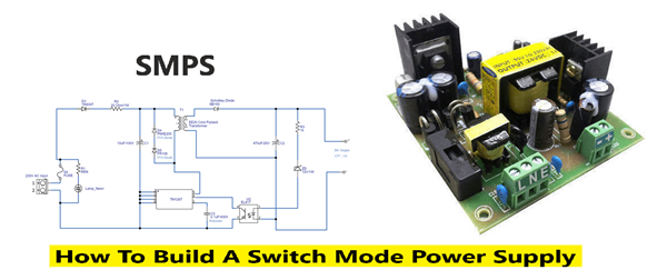
Understanding switched-mode power supplies (SMPS)
A switched-mode power supply (SMPS) is an electronic circuit that converts power efficiently using high-frequency switching transistors (MOSFETs) rather than linear regulation. By rapidly turning components on and off (switching), it reduces energy loss, resulting in high efficiency (> 85%), smaller size, and lighter weight compared to traditional linear power supplies How an SMPS Works
Unlike linear supplies that burn off excess energy as heat, an SMPS regulates voltage by varying the switching duty cycle—the ratio of "on" time to "off" time.
Core Working Principle The operation can be broken down into five primary stages:
Key Advantages
Converter topology basics
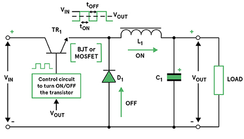
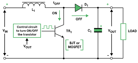
Figure 1: A forward-mode or buck step-down switching converter There are several different converter topologies in use, some of them more popular than others. Each has a slightly different configuration of magnetic components, such as inductors and transformers, and capacitors. Text-book topologies include the buck converter and the boost converter, and they are convenient examples to illustrate the basic principles of a switched-mode converter circuit. A buck converter, also termed forward-mode, is used to step down the input voltage. Figure 1 (right) shows a simplified circuit noting the use of an inductor (L) and capacitor (C) on the output circuit. The semiconductor switch (TR1) represents the fast switching action of a MOSFET driving into saturation or entirely off. When TR1 is conducting, the diode (D) is reverse biased, and current flows to the load. This charges up the capacitor C, through the inductor (L) which opposes the flow, creating a magnetic field. When TR1 stops conduction, the magnetic field in L collapses, the diode (D) becomes forward biased forcing the current through the load, and during the same period the capacitor (C) also discharges its held charge to the load. The combination of the inductor and capacitor values create an LC filter that serves to smooth out any ripple created by the switching actions. The boost converter (see Figure 2, below) is another type of popular topology, this time suiting increasing or 'boosting' the input voltage to create a higher output voltage. Unlike the buck converter, where the switching transistor is in series with the input voltage, in the boost circuit it’s in parallel with the input and connected to the input via an inductor. The capacitor continues to be across the load, serving to hold-up the output voltage while the transistor is conducting. The inductor’s collapsing field flows to the output while the transistor is off.
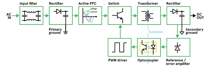
Figure 2: A simplified boost converter circuit A combination of the buck and boost topologies is the buck/boost converter that’s capable of stepping up or down the input voltage. Note that, from an aspect of safety, none of the above topologies uses a transformer - described as a non-isolated converter - to isolate the input voltage from the output. They also share a common ground connection. There are several topologies in use for AC-DC power supplies that provide isolation and are highly energy efficient in operation, the most popular being the flyback and quasi-resonant methods. The architecture of a typical switched-mode power supply
Figure 3: The functional blocks of an example AC-DC switched-mode power supply (SMPS) Common Applications
SMPS vs. Linear Power Supplies
While SMPS technology can introduce higher electrical noise (ripple) and requires more complex design, its superior efficiency and power density make it the dominant choice for modern electronics.
|

+(39) 347 051 5328
Italy - Kazakhstan


09.00am to 18.00pm
About
We offer the best and economical solutions, backed by 27+ years of experience and international standards knowledge, echnological changes, and industrial systems.
Our Services
Marketing Materials


Marketing Materials1


