How does a hydraulic valve actuator work in an oil and gas industry
A hydraulic actuator valve in oil and gas systems uses pressurized hydraulic oil to move a piston or vane, generating high-force linear or rotary motion to open, close, or throttle large valves. It provides stable, precise, and powerful control for critical applications like wellheads and pipelines, often using single-acting (spring-return) or double-acting (fluid-driven both ways) mechanisms.A hydraulic actuator valve in oil and gas system uses pressurized hydraulic oil to move a piston or vane, generating high-force linear or rotary motion to open, close, or throttle large valves. It provides stable, precise, and powerful control for critical applications like wellheads and pipelines, often using single-acting (spring-return) or double-acting (fluid-driven both ways) mechanisms.
This video demonstrates how a hydraulic actuator uses pressurized fluid to move a piston and operate a valve:
Key Components and Working Principles
Power Source: A hydraulic pump provides high-pressure oil, essential for handling high-pressure, heavy-duty applications, making it more powerful than pneumatic systems.
Actuation Mechanism: The oil pushes a piston, which drives a stem to control the valve's position.
Double-Acting vs. Single-Acting: Double-acting actuators use oil pressure to move in both directions, whereas single-acting use a spring or gravity to return to a safe position (e.g., Fail-Safe Closed/Open).
Control Mechanism: A Directional Control Valve (DCV) (such as a 4/2-way valve) switches the flow of oil to different sides of the piston, changing the direction of movement.
Applications in Oil and Gas
Wellhead Operations: Used for safety shutdowns and controlling flow, often in remote locations, as mentioned in this YouTube video.
Pipeline Management: Used for operating large ball or gate valves in, for example, this PT Valvindo Megah article.
Production Facilities: Controlling high-pressure fluids, say this POV Valve article
Core Mechanism
The operation generally follows these steps:
Pressure Generation: A hydraulic pump—the power source—pressurizes the oil and moves it from a reservoir into the system.
Signal Conversion: A control signal (electrical or manual) is sent to a control valve or solenoid, which directs the pressurized fluid into specific chambers of the actuator.
Mechanical Motion: The fluid enters a cylinder and pushes against a piston. This movement is then transferred to the valve stem:
Linear Motion: Directly moves a gate or globe valve up and down.
Rotary Motion: Uses mechanisms like scotch yoke or rack-and-pinion to turn the stem for ball or butterfly valves.
Advantages and Disadvantages
Advantages: High force/torque output, precise positioning, and consistent operation for heavy-duty systems.
Disadvantages: High cost, complex maintenance, and risk of contamination.
Key Benefits in Oil & Gas
High Force & Torque: Necessary for operating massive pipeline isolation valves or subsea wellhead "Christmas trees".
Precision: Because oil is incompressible, it allows for extremely accurate throttling (partial opening) and immediate response times.
Safety & Fail-Safes: Systems often include hydraulic locking to hold a valve's position or relief valves to prevent over-pressurization.
Hydraulic Control Panel
A hydraulic control panel in the Oil & Gas industry uses pressurized hydraulic fluid (oil) to remotely operate, control, and position actuators, allowing for precise, high-torque movement of large valves . It manages flow, pressure, and direction via solenoids or manual valves, ensuring safe, automated, and emergency shutdown capabilities
Key Aspects of Hydraulic Control Panels
Function: The panel acts as a central hub to direct high-pressure oil to the actuator, which converts fluid energy into linear or rotary mechanical motion to open, close, or throttle a valve.
Components: Typically includes a hydraulic pump (to pressurize oil), directional control valves, pressure relief valves (for safety), accumulators (for emergency power), filters, gauges, and solenoids.
Operation: When a signal (electrical or manual) activates a pilot valve, it directs pressurized oil to one side of the actuator piston, pushing it to move the valve stem.
Safety & Control: In the event of a power failure or emergency, specialized panels can use stored pressure to return valves to a default "safe" position (fully open or closed).
Advantages: Ideal for heavy-duty applications, high force requirements, and precise positioning compared to pneumatic systems.
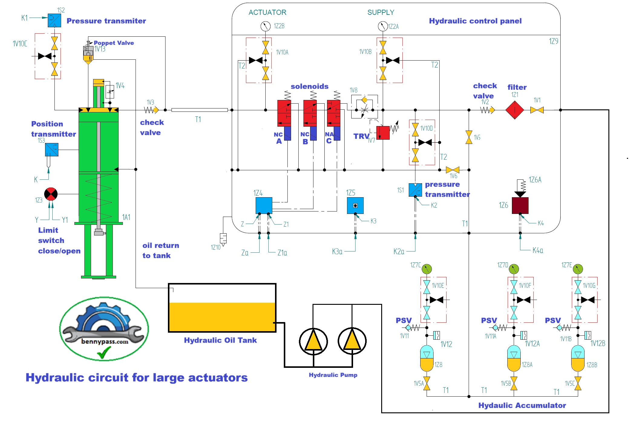
For more details see figure below
Figure above shows a schematic of a large valve such a HIPPS (High-Integrity Pressure Protection System). The system is equipped with 3 solenoids, 2 of them are used for ESD (close/open) and one used for the partial stroke. the difference between each other is that: Solenoid A and B are normally close and C is normally open. Why this difference between solenoids? The solenoid C is used for the partial stroke and will energize only when the partial stroke will be activate. If all three are normally closed, during partial stroke, as soon the solenoid C fails, the valve will close fully, causing a significant impact on production. Never install NC (normally close) solenoid to the partial stroke.
Working Principle step by step
Note: We suppose that already is present the hydraulic pressure on the accumulator and pumps working in auto mode to maintain the pressure
Open the valve:
As soon the Pumps pressurize the interie circuit (including the accumulators), the system is ready to operate the valve
As soon as Solenoids A and B are energized, the hydraulic oil will flow through check valve 1V3 to the actuator. Simultaneously, the hydraulic oil pilots the poppet valve, which closes the vent side. In this condiction the actuator will move to open the valve
Partial Stroke activation
In normal condiction means valve open (solenoid A-B (NC)) and solenoid C de-enerize (NO)
As soon as solenoid C (NO) is energized, hydraulic oil is released from its vent port, causing a pressure drop at the poppet valve pilot. The hydraulic oil cannot flow back through the solenoid vent due to check valve IV3. To release hydraulic oil from the actuator, the internal piston of the poppet valve—which was previously pressed into its seat by pilot pressure—will lift up as the pilot pressure drops. This action opens the vent port to the return tank, releasing the hydraulic oil from the actuator and closing the valve.
As soon as the the actuator move to the close direction, the open indication limit switch change status of contact, including the analog fileback which will reaches 80% of position, therebefore, the controller de-energize the solenoid C and hydraulic oil will pressurize the pilot of poppet valve and internal piston will move and close the vent port, consequently, the hydraulic oil flowing again inside actuator and re-open the valve fully
Note: To protect the system in case a partial stroke test fails and risks causing the valve to close fully (impacting production), a controller (PLC) with a timer is used to detect if the valve gets stuck or a limit switch is damaged during partial stroke test. There is a timer that controls how many seconds it takes to deactivate the limit switch open position or the analog feedback during valve movement, therefore, if the limit switch opens or feedback does not reach the position pre-established within the time set in the PLC, the partial stroke fails, solenoid C will be de-energized, and the valve will open fully again. This is a very important function for production. For more details see video attached here
Close the valve
To close the valve require just to de-energize the solenoid A and B and valve will close full through the vent port of poppet valve (as described in the partial stroke test )
Conclusion
We advise against using solenoids A and B for partial stroke testing. If the fuse blows/fails during the test, the NC (Normally Closed) solenoids will vent hydraulic oil, causing the valve to close fully.
The N2 accumulators normally are used for operate the valve 3 time without hydraulic supply.
Have a Questions?
+(39) 347 051 5328
Visit Our Company
Italy - Kazakhstan
Working Hours
09.00am to 18.00pm
About
We offer the best and economical solutions, backed by 27+ years of experience and international standards knowledge, echnological changes, and industrial systems.