Flange Bolt Torque Sequence and Torque Table – A
Complete Bolt Tightening Procedure
Flange joints require proper tightening to avoid the leak of the fluid from the joint. Bolt tightening sequence or torque sequence is defined in torque tightening procedure. Most company has their Flange bolt torque tightening procedure that used during construction and operation of the plant.
When the bolt loading requires a torque higher than 678 Nm (500 ft-lbs.) to be applied, hydraulic bolt torqueing is recommended.
The torque value is dependent on the friction between the threads of stud bolt and nut head, this friction can be affected by the application of a lubricant or any plating (e.g. Cadmium or Zinc) applied to the stud threads. The bolting standard will define whether the torque value is for a dry or lubricated stud/bolt thread. If a bolt is torqued rather than the nut then the torque value should be increased to compensate for the additional friction – bolt should only be torqued if they are fitted in clearance holes.
The bolts shall be tightened by torque control, using the Anti-seize lubricant shall be used such as Molykote or equivalent, before installation. The specified method of bolt tightening is equally applicable to coated, galvanized and ungalvanized bolts.
|
 HARRIS 25-15C-510 Regulator Acetylene HARRIS 25-15C-510 Regulator Acetylene
|
|
|
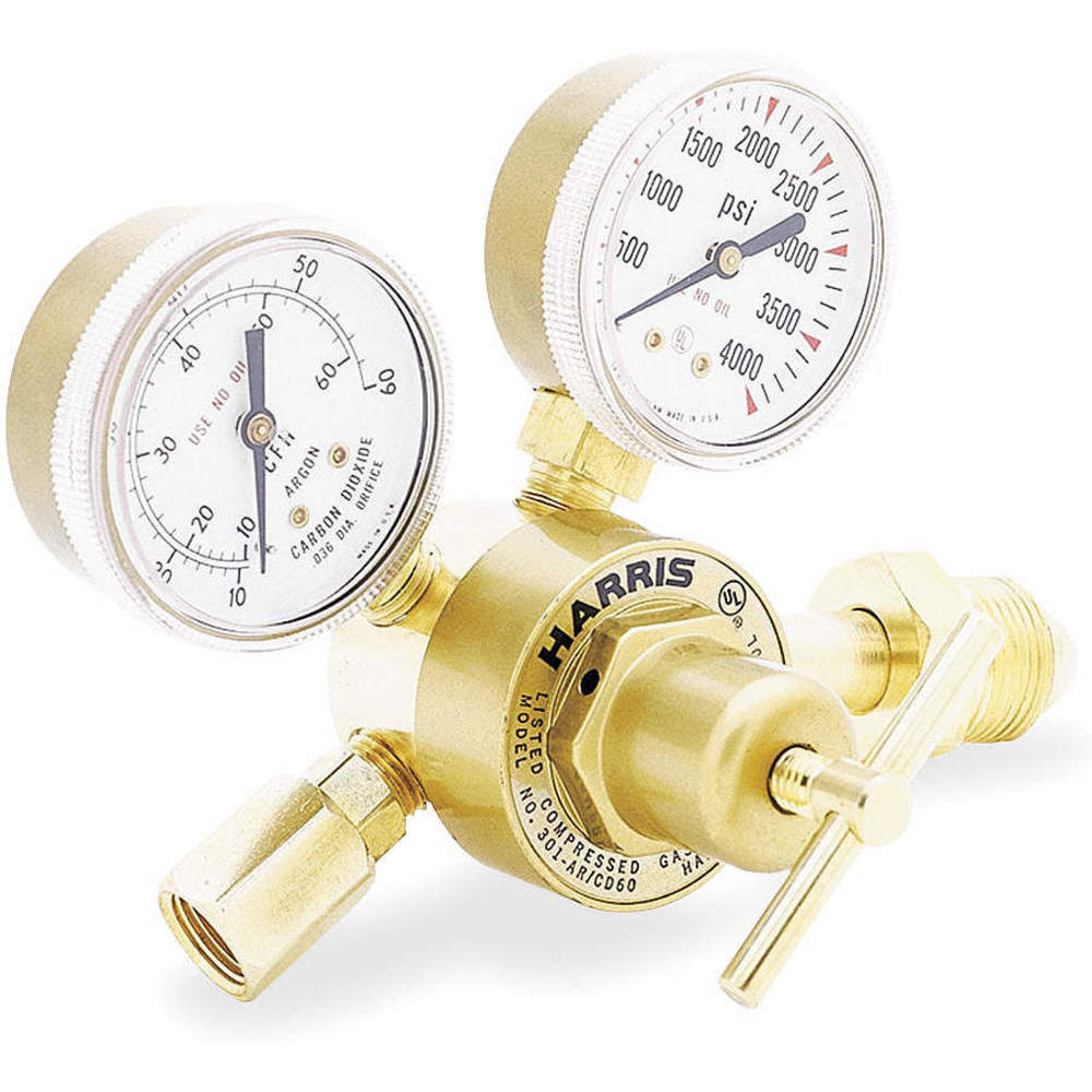
 HARRIS 301-CD60-320 Regulator Flow Gauge HARRIS 301-CD60-320 Regulator Flow Gauge
|
|
|
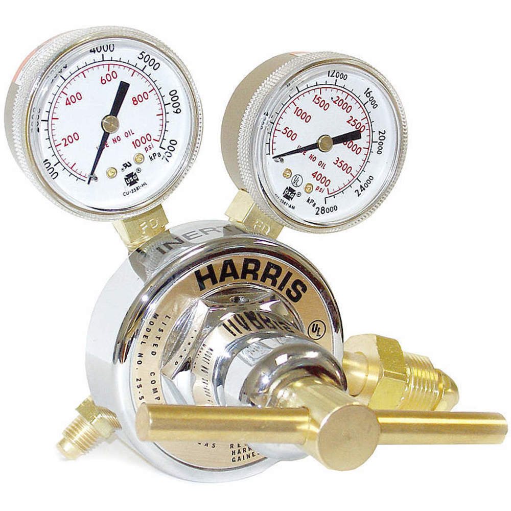
 HARRIS 301-AR60-580 Regulator Flow Gauge HARRIS 301-AR60-580 Regulator Flow Gauge
|
|
|
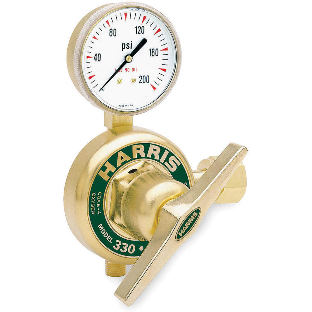 HARRIS 330-125-320 Regulator 0-125 Psi HARRIS 330-125-320 Regulator 0-125 Psi
|
|
|
 HARRIS 425-50-540 Regulator Oxygen HARRIS 425-50-540 Regulator Oxygen
|
|
|
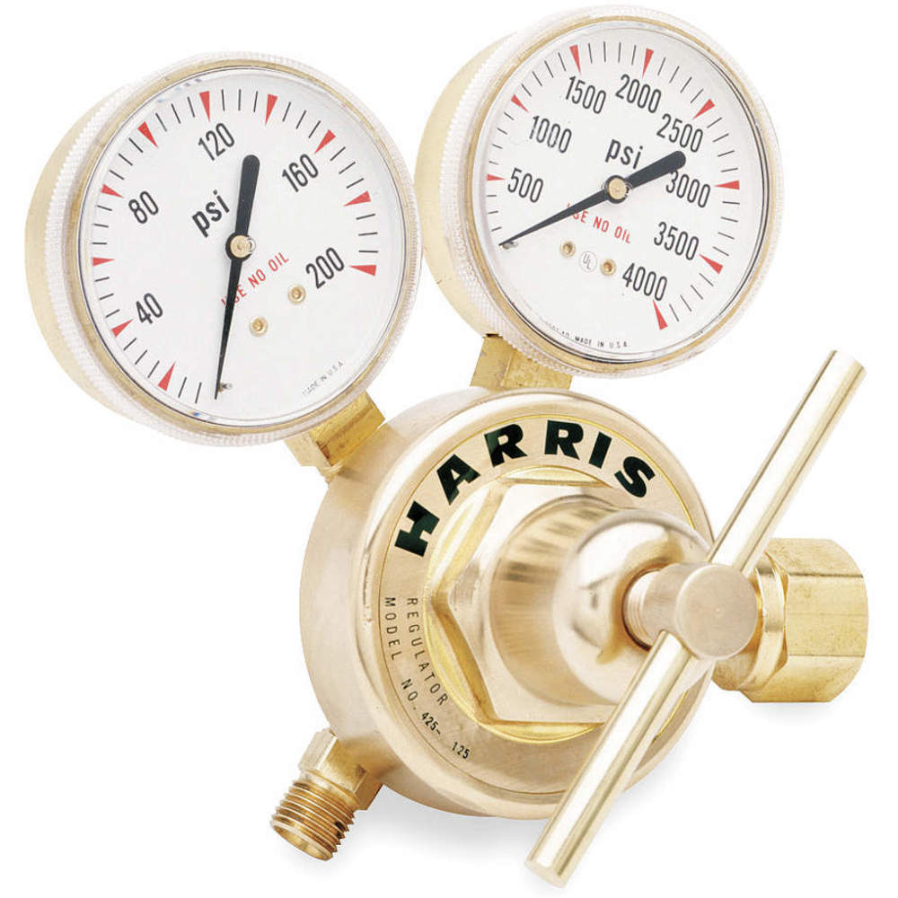
 HARRIS 425-125-320 Regulator 0-125 Psi HARRIS 425-125-320 Regulator 0-125 Psi
|
|
|
 HARRIS 25-15C-510 Regulator Acetylene HARRIS 25-15C-510 Regulator Acetylene
|
|
|
 HARRIS 25-50C-510P Regulator Propane HARRIS 25-50C-510P Regulator Propane
|
|
Pre-checks for Bolt Tightening
Flange Condition
- Check conditions of flange faces for scratches, dirt and scale.
- Check for corrosion pitting and tool marks.
- Inspect the gasket seating surfaces.
- Check the areas on the flange where the nuts will seat, it should be flat and free from pitting and excessive wear.
- RTJ Grooves must be kept clean, corrosion free & undamaged.
Acceptable imperfection of Pipe flange raised face are given in ASME 16.5 table 3. Refer the table for Permissible Imperfections in Flange Facing Finish for Raised Face Flange.
|
Maximum Radial Projection of Imperfections that are |
| Size in Inch |
Size in mm |
No Deeper Than the Bottom of the Serrations, mm |
Deeper Than the Bottom of the Serrations, mm |
| 1/2 |
15 |
3.0 |
1.5 |
| 3/4 |
20 |
3.0 |
1.5 |
| 1 |
25 |
3.0 |
1.5 |
| 1 1/4 |
32 |
3.0 |
1.5 |
| 1 1/2 |
40 |
3.0 |
1.5 |
| 2 |
50 |
3.0 |
1.5 |
| 2 1/2 |
65 |
3.0 |
1.5 |
| 3 |
80 |
4.5 |
1.5 |
| 3 1/2 |
90 |
6.0 |
3.0 |
| 4 |
100 |
6.0 |
3.0 |
| 5 |
125 |
6.0 |
3.0 |
| 6 |
150 |
6.0 |
3.0 |
| 8 |
200 |
8.0 |
4.5 |
| 10 |
250 |
8.0 |
4.5 |
| 12 |
300 |
8.0 |
4.5 |
| 14 |
350 |
8.0 |
4.5 |
| 16 |
400 |
10.0 |
4.5 |
| 18 |
450 |
12.0 |
6.0 |
| 20 |
500 |
12.0 |
6.0 |
| 24 |
600 |
12.0 |
6.0 |
Flange Alignment
Visually examine the flange alignment to ensure that an acceptable fit has been obtained. While aligning flanges, make sure that there are no residual stresses in the joint. The use of heat correction for the alignment of flanges is strictly prohibited.
- Flange faces should be parallel and aligned.
- The flange bolt holes should be in line so that the bolts will pass freely.
Nut, Stud or Bolt Checks
- Visually examine nuts & Stud/bolts before installation to assure they are free from defects such as corrosion, damage threads etc. Nut-bolts with damaged threads should not be used.
- Check the length of the stud or bolt to avoid short bolting and excessive threads. Flange bolts shall be furnished in sufficient length to allow the use of bolt tensioning equipment or spades, spacers, drip rings and wafer valves, and the associated extra gaskets.
- Visually examine studs and nuts after cleaning to ensure free from burrs. Studs and nuts shall be cleaned using a wire brush to remove any dirt on the threads. Lubricant (MOLYKOTE) shall be applied on threads and nuts to flange contact surfaces. Lubricant shall not be used in the gasket and the gasket seating area.
- The bolt and nut material grades should be correctly identified before they are used.
- Bolts and nuts can only be reused if it is known that they have not been overloaded or exceeded their yield point.
- When assembling the nut on the bolt, the nut identification marking must always point outwards.
Gasket Checking
- Do not use sealing compound, grease or other paste or adhesive on gasket or flange faces.
- While gasket insertion, it shall not be forced into the gasket seat between the mating flange faces. Once the gasket is seated the mating flanges are brought together carefully without shaking the gasket off the seat, install all studs and run-up all nuts hand tight.
- Visually examine gaskets, before installation, to assure they are free from defects.
- Color coding shall be maintained as per the rate and type of gasket provided by the manufacture.
- Clean gasket seating face using a wire brush.
- Make sure the material is as specified, look for any possible defects or damage in the gasket such as folds or creases.
- All Soft material gaskets should be replaced with new ones whenever an opened joint is to be closed again.
- The spiral wound gasket shall be used only once.
Flange Bolt Torque Sequence
Torque bolts and nuts in a “CRISS-CROSS” sequence using a minimum of three torquing passes and the maximum bolt stress as defined. Torque sequence here.
- PASS 1: Torque to a maximum of 30% of the final torque value in accordance with the torque sequence. Check that gasket is getting compressed uniformly.
- PASS 2: Torque to a maximum of 60% of the final torque value.
- PASS 3: Torque to the final torque value (100%).
After the three basic torque passes are completed, repeat torquing the nuts at least once using the final torque in a “CRISS-CROSS” manner until no further rotation of the nut is observed.
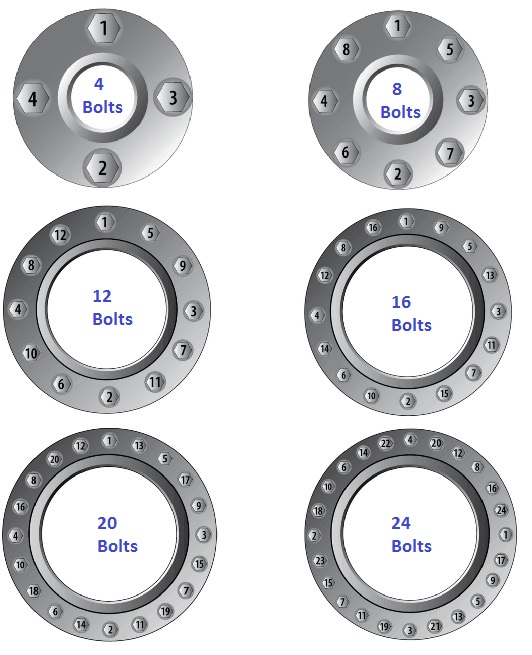
For easy handling, bolt numbering shall be done clockwise around the flange with the following sequence.
| 4 bolt Flange |
1,3,2,4 |
| 8 bolt Flange |
1,5,3,7,2,6,4,8 |
| 12 bolt Flange |
1,7,4,10,2,8,5,11,3,9,6,12 |
| 16 bolt Flange |
1,9,5,13,3,11,7,15,2,10,6,14,4,12,8,16 |
| 20 bolt Flange |
1,11,6,16,3,13,8,18,5,15,10,20,2,12,17,4,14,9,19 |
| 24 bolt Flange |
1,13,7,19,4,16,10,22,2,14,8,20,5,17,11,23,6,18,12,24,3,15,9,21 |
| 28 bolt Flange |
1,15,8,22,4,18,11,25,6,20,13,27,2,16,9,23,5,19,12,26,3,17,10,24,7,21,14,28 |
| 32 bolt Flange |
1,17,9,25,5,21,13,29,3,19,11,27,7,23,15,31,2,18,10,26,6,22,14,30,8,24,16,32,4,20,12,28 |

|


