
DP- Pad cell Transmitter with Interface Level Configuration Differential pressure (DP) transmitters are used to measure the interface of two fluids with different specific gravities (S1 & S2). To make an interface measurement, the overall level must be at or above the low pressure tap at all times. It is important that the level be large enough to create a reasonable DP between the two specific gravity extremes. This measurement can be done with or without remote seals. However, from a maintenance point of view, it may be easier to use a remote seal assembly; keeping the wet leg at a constant height can be difficult in some applications.
To determine the calibration range of transmitter, need consider four assumptions, all described below:
The measured level is composed of a combination of the two fluids: L = L1S1 + L2S2 When the tank is filled with the lighter fluid, the transmitter will be at 4 mA (or 0% of span) and L2 = L: HP = L2S2 + dSf LP = dSf + hSf At 4 mA, DP = HP – LP = L2S2 – hSf When the tank is filled with the heavier fluid, the transmitter will be at 20 mA (or 100% of span) and L1 = L: HP = L1S1 + dSf LP = dSf + hSf At 20 mA, DP = HP – LP = LS1 – hSf
The tools below is used to calculate the DP transmitter ranges for interface measurement application
For calibration range of DP use the formula below: The Transmitter 4ma or LRV formula ∆Pmin or 4ma = LS2 – HSf The Transmitter 20ma or URV formula ∆Pmax or 20ma = LS1 – HSf The automatic calculation (DP) above can be used to found the internface level in the second automatic calculation below (second step)
In the second step below there are four paramiters to add which are:
The Interface Level (I) is the value in mm that are now in the vessel.
Interface Calculation
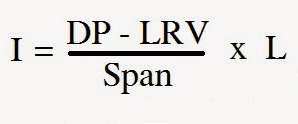
The formula used for calculation the interface in mm is:
below all the abraviation H = Distance between taps L = Total Measured Level S1 = Specific gravity of lighter fluid S2 = Specific gravity of heavier fluid Sf = Specific gravity of reference leg Measured DP= After transmitter calibration, present DP value Span = Difference between absolute of maximum and minimum range LRV = Lower range value of transmitter in DP scale I = Interface level
Advantages
Limitations
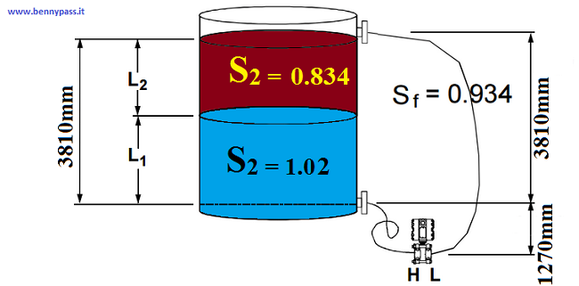
Example calculation: A vessel requires an interface measurement where: capacity of vessel 3810mm fluid S1 the specific gravity is 1.0 fluid S2 the specific gravity is 1.08 below the figure with all dettail:
At 4mA, DP = L2S2 – hSf DP= (3810 * 0.834 / 1.02 / 10 ) - (3810 * 0.934 / 1.02 / 10 ) So at 4 mA = 37.35 mbar DP At 20mA, DP = LS1 – hSf DP= (3810 * 1.02 / 1.02 / 10 ) - (3810 * 0.934 / 1.02 / 10 ) So at 20 mA = 54.6 mbar DP
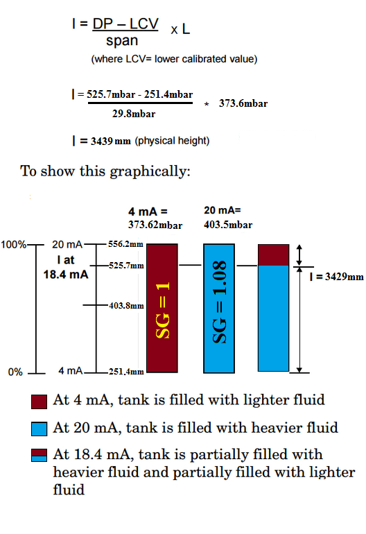
Conclusion The calibrated span is 24.7 to 54.6mbar. When the transmitter reads 24.7mbar, the tank is filled with the lighter fluid. When the transmitter reads 54.6mbar, the tank is filled with the heavier fluid. To determine where the interface is located (mixture of fluids), reading the DP from Transmitter (% of span). For example: If the out transmitter is 18.4ma or DP is 51.55mbar use formula below
|

+(39) 347 051 5328
Italy - Kazakhstan


09.00am to 18.00pm
About
We offer the best and economical solutions, backed by 27+ years of experience and international standards knowledge, echnological changes, and industrial systems.
Our Services
Marketing Materials


Marketing Materials1


