
|
Controller square root or linear flow rate Indroduction The most used DP flow Meter type are:
These flowmeter types all require the measurement of a differential pressure that results from an obstruction of flow or from an impact of flow on an object. The venturi flowmeter uses a variable area flow tube (or throat) to develop a differential pressure upstream and downstream of the throat. The orifice plate uses a barrier plate with a hole cut into it, and the differential pressure across the orifice is measured to determine flow rate. The pitot tube uses the pressure of the fluid at an impact nozzle and a static pressure measurement to determine flow rate. In all three of these cases, flow is proportional to the square root of the measured pressure differential. Therefore, when measuring the output of an orifice plate meter, a venturi meter, or pitot tube, square root extraction is necessary to linearize the output for use in the control system. This square root extraction can be done at the device (transmitter) or at the control system (configuration of analog input), but should not be done at both places Normally square root should be apply on the control system, while the transmitter remain in linear. Some pressure measurements are used to indirectly derive another type of measurand. One of these is the Rate of Flow of a gas or liquid. The flow rate along a closed pipe is directly proportional to the square root of the pressure drop or differential pressure between two points. Since the relationship is non-linear there is a greater change in flow at low pressures compared to higher ones. In order to optimize the resolution of flow measurement the output on some differential pressure transmitters can be altered so that it is directly proportional to the flow rate rather than the differential pressure.
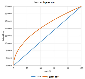
Main characteristics The Photo below showing the difference between square root flow rate and linear flow rate
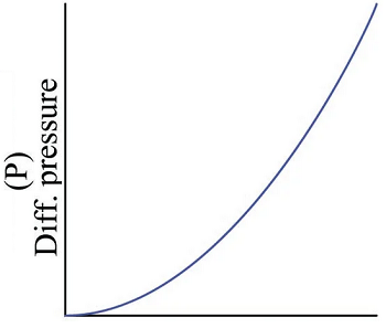
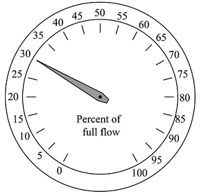
To write this as a proportionality, we relate flow rate (Q) to pressure (P) as follows (the constant K accounts for unit conversions and the geometries of the orifice plate and pipe): P=KQ2 This is a practical problem for us because our intent is to use pressure measurement (P) as an indirect (inferred) indication of flow rate (Q). If the two variables are not directly related to one another, we will not be able to regard one as being directly representative of the other. To make this problem more clear to see. Let's take a practical example with a simple pressure Gauge connected across the restriction with indication in percentage. Below the foto with pressure guage
Consider a pressure gauge such as the one shown above, registering 20 percent on a linear scale at some amount of flow through the pipe. What will happen if the flow rate through that pipe suddenly doubles? An operator or technician looking at the gauge ought to see a new reading of 40 percent, if indeed the gauge is supposed to indicate flow rate. However, this will not happen. Since the pressure dropped across the orifice in the pipe increases with the square of flow rate, a doubling of flow rate will actually cause the pressure gauge reading to quadruple! In other words, it will go from reading 20% to reading 80%, which is definitely not an accurate indication of the flow increase.
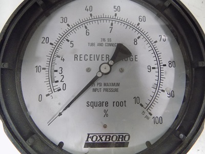
A couple of simple solutions exist for addressing this problem. One is to re-label the pressure gauge with a “square root” scale. Examine this photograph of a 3-15 PSI receiver gauge:
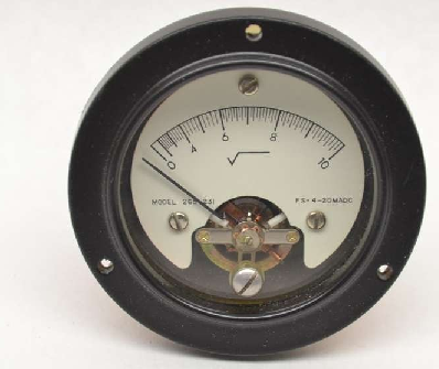
Now, a doubling of fluid flow rate still results in a quadrupling of needle motion, but due to the nonlinear (inner) scale on this gauge this needle motion translates into a simple doubling of indicated flow, which is precisely what we need for this to function as an accurate flow indicator. If the differential pressure instrument outputs a 4-20 mA analog electronic signal instead of a 3-15 PSI pneumatic signal, we may apply the same “nonlinear scale” treatment to any current meter and achieve the same result see Photo below
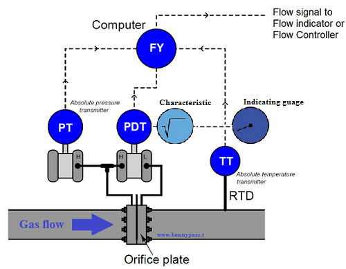
There is others method but a more sophisticated solution to the “square root problem” is to use a computer to manipulate the signal coming from the differential pressure instrument so the characterized signal becomes a direct, linear representation of flow. In other words, the computer square-roots the pressure sensor’s signal in order that the final signal becomes a direct representation of fluid flow rate:
Normally the new version of transmitters are with digital display selectable square root or linear, o addirittura nei trasmettitori vecchi ce il galvanometro come nella foto sopra Both solutions achieve their goal by mathematically “un-doing” the nonlinear (square) function intrinsic to the physics of the orifice plate with a complementary (inverse) function. This intentional compounding of inverse functions is sometimes called linearization, because it has the overall effect of making the output of the instrument system a direct proportion of the input:
The following formula can be used for converting a linear 4-20mA current loop output to a square root extraction type: [Output Sq Rt] = 4mA + (4 x Square Root of ([Output Linear] – 4mA)) The reverse formula for converting a square root extraction output to a linear one is: [Output Linear] = 4mA + (([Output Sq Rt] – 4mA)^2 / 16)
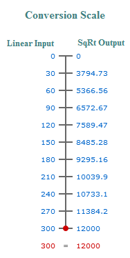
Below the tool to convert the transmitter Linear % signal into the equivalent square root % signal.
let's take a practical example: We have a transmitter with range 0 - 300 pascals which corresponds 0 to 12000m3/h What flow rates should we expected to see at different pressures over the 0 to 300 Pa range? The following conversion scale shows 10 points over the 0 to 300 Pa range for you to compare with actual flow beingmeasured.
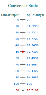
SqRt extraction to convert inH20 pressure to mmscfd flow: What is the exact calculation that is performed when we are selecting square root as a transfer function for flow measurement? For example, if 0-100 mmscfd (million standard cubic feet per day) is the flow range and 0-100 inH2O is the differential pressure sensor range. When the DP is 50 inH2O, the flow will be 50 mmscf if the linear range is selected. In the case of square root what will be the flow when the DP is 50 inH2O? The flow generated by 50 inH2O is: 50 inH2O = 70.710625 mmscf
For calculation use the formula below: SRR = ((LI - LLI) / (HLI - LLI))1/2 x (HSO - LSO) + LSO
Linear to SqRt % span formula What is the formula for converting a linear reading as percentage of span to a square root reading? The formula is as follows: %SqRtSpan = √ (%LinSpan/100) x 100
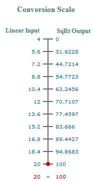
4-20mA linear to 0-100% flow How do you convert mA to percentage square root extraction of flow measurement?Enter the following into this calculator for a 4-20mA signal to square root percentage conversion: Linear Input (4-20mA)
Square Root Extraction Output (%)
This is a 10 point scale showing the conversion values:
Conclusion An unfortunate consequence of this quadratic relationship is that a pressure-sensing instrument connected to such a flow element will not directly sense flow rate. Instead, the pressure instrumen will be sensing what is essentially the square of the flow rate. The instrument may register correctly at the 0% and 100% range points if correctly calibrated for the flow element it connects to, but it will fail to register linearly in between. Any indicator, recorder, or controller connected to the pressure-sensing instrument will likewise register incorrectly at any point between 0% and 100% of range, because the pressure signal is not a direct representation of flow rate. In order that we may have indicators, recorders, and controllers that actually do register linearly with flow rate, we must mathematically “condition” or “characterize” the pressure signal sensed by the differential pressure instrument. Since the mathematical function inherent to the flow element is quadratic (square), the proper conditioning for the signal must be the inverse of that: square root. Just as taking the square-root of the square of a number yields the original number9, taking the square-root of the differential pressure signal – which is itself a function of flow squared – yields a signal directly representing flow.
|


+(39) 347 051 5328
Italy - Kazakhstan


09.00am to 18.00pm
About
We offer the best and economical solutions, backed by 27+ years of experience and international standards knowledge, echnological changes, and industrial systems.
Our Services
Marketing Materials


Marketing Materials1


