
The characteristic of Resistance
|
Resistors with 4 coloured rings Below is the table with four colours resistance, including the values
For the correct reading code, it is necessary to position the resistor with the silver or gold ring on the right and proceed with reading the colours from left to right. The first two rings correspond to units and tens. The third ring indicates the number of zeros that are to be added. While the first set of rings indicates the resistive value, the fourth ring indicates the tolerance, which is the percentage more or less of the actual value with respect to the value declared by the rings (+/-).
ORANGE - GREEN - BLUE - GOLDEN
Resistors with 5 coloured rings Below is the table with the five colours' Resistance, including the values (precision resistance)
The reading mode is identical to the one that is shown in the previous table.
Resistors with 6 coloured rings Below is the table with six colours of Resistance, including the values and temperature coefficient. This type of Resistance is not very frequently used and is only useful in certain situations.
Multiple
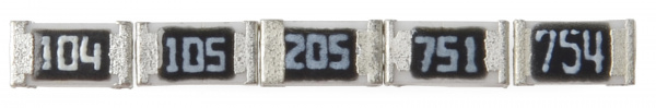
Decoding Surface-Mount MarkingsSMD resistors, like those in 0603 or 0805 packages, have their own way of displaying their value. There are a few common marking methods you'll see on these resistors. They'll usually have three to four characters – numbers or letters – printed on top of the case. If the three characters you're seeing are all numbers, you're probably looking at an E24-marked resistor. These markings actually share some similarities with the colour-band system used on the PTH resistors. The first two numbers represent the first two most-significant digits of the value. The last number represents a magnitude.
In the above example picture, resistors are marked 104, 105, 205, 751, and 754. The resistor marked with 104 should be 100kΩ (10x104), 105 would be 1MΩ (10x105), and 205 is 2MΩ (20x105). 751 is 750Ω (75x101), and 754 is 750kΩ (75x104). Another common coding system is E96, and it's the most cryptic of the bunch. E96 resistors will be marked with three characters – two numbers at the beginning and a letter at the end. The two numbers tell you the first three digits of the value by corresponding to one of the not-so-obvious values on this lookup table.
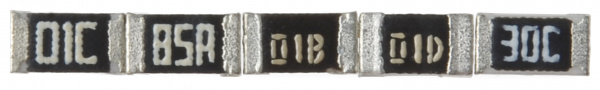 So a 01C resistor is our good friend, 10kΩ (100x100), 01B is 1kΩ (100x10), and 01D is 100kΩ. Those are easy. Other codes may not be. 85A from the picture above is 750Ω (750x1) and 30C is actually 20kΩ. Power RatingThe power rating of a resistor is one of the more hidden values. Nevertheless, it can be important, and it's a topic that'll come up when selecting a resistor type. Power is the rate at which energy is transformed into something else. It's calculated by multiplying the voltage difference across two points by the current running between them and is measured in units of a watt (W). Light bulbs, for example, power electricity into light. But a resistor can only turn electrical energy running through it into heat. Heat isn't usually a nice playmate with electronics; too much heat leads to smoke, sparks, and fire! Every resistor has a specific maximum power rating. In order to keep the resistor from heating up too much, it's important to make sure the power across a resistor is kept under its maximum rating. The power rating of a resistor is measured in watts, and it's usually somewhere between ⅛W (0.125W) and 1W. Resistors with power ratings of more than 1W are usually referred to as power resistors and are used specifically for their power-dissipating abilities.
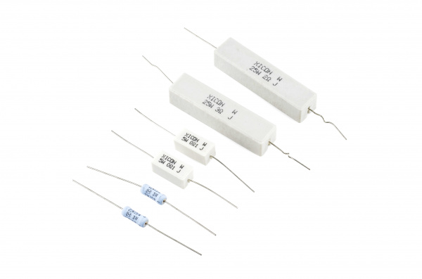
Finding a resistor's power ratingA resistor's power rating can usually be deduced by observing its package size. Standard through-hole resistors usually come with ¼W or ½W ratings. More special purpose, power resistors might actually list their power rating on the resistor.
These power resistors can handle a lot more power before they blow. From top-right to bottom-left, there are examples of 25W, 5W and 3W resistors, with values of 2Ω, 3Ω 0.1Ω and 22kΩ. Smaller power resistors are often used to sense current.
The power ratings of surface mount resistors can usually be judged by their size as well. Both 0402 and 0603-size resistors are usually rated for 1/16W, and 0805s can take 1/10W.
Measuring power across a resistorPower is usually calculated by multiplying voltage and current (P = IV). But, by applying Ohm's law, we can also use the resistance value in calculating power. If we know the current running through a resistor, we can calculate the power as follows:
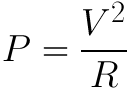
Or, if we know the voltage across a resistor, the power can be calculated as:
Series and Parallel ResistorsResistors are paired together all the time in electronics, usually in either a series or parallel circuit. When resistors are combined in series or parallel, they create a total resistance, which can be calculated using one of two equations. Knowing how resistor values combine comes in handy if you need to create a specific resistor value.
Series resistorsWhen connected in series, resistor values add up.
N resistors in series. The total Resistance is the sum of all series resistors.
So, for example, if you just have to have a 12.33kΩ resistor, seek out some of the more common resistor values of 12kΩ and 330Ω, and butt them up together in series.
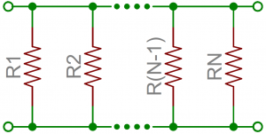
Parallel resistorsFinding the Resistance of resistors in parallel isn't relatively so easy. The total Resistance of N resistors in parallel is the inverse of the sum of all inverse resistances. This equation might make more sense than that last sentence:
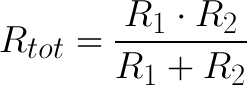
N resistors in parallel. To find the total Resistance, invert each resistance value, add them up, and then invert that. (The inverse of Resistance is actually called conductance, so put more succinctly: the conductance of parallel resistors is the sum of each of their conductances). As a special case of this equation: if you have just two resistors in parallel, their total Resistance can be calculated with this slightly-less-inverted equation:
As an even more special case of that equation, if you have two parallel resistors of equal value, the total Resistance is half of their value. For example, if two 10kΩ resistors are in parallel, their total Resistance is 5kΩ. A shorthand way of saying two resistors are in parallel is by using the parallel operator: ||. For example, if R1 is in parallel with R2, the conceptual equation could be written as R1||R2. Much cleaner and hides all those nasty fractions!
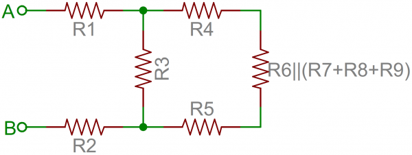
Resistor networksAs a special introduction to calculating total resistances, electronics teachers just love to subject their students to finding that of crazy, convoluted resistor networks. A tame resistor network question might be something like: "what's the resistance from terminals A to B in this circuit?"
To solve such a problem, start at the back-end of the circuit and simplify towards the two terminals. In this case, R7, R8 and R9 are all in series and can be added together. Those three resistors are in parallel with R6, so those four resistors could be turned into one with a resistance of R6||(R7+R8+R9). Making our circuit: Now the four right-most resistors can be simplified even further. R4, R5, and our conglomeration of R6 - R9 are all in series and can be added. Then those series resistors are all in parallel with R3.
And that's just three series resistors between the A and B terminals. Add them on up! So the total Resistance of that circuit is R1+R2+R3||(R4+R5+R6||(R7+R8+R9)).
Example ApplicationsResistors exist in just about every electronic circuit ever. Here are a few examples of circuits which heavily depend on our resistor friends.
LED Current LimitingResistors are key in making sure LEDs don't blow up when power is applied. Connecting a resistor in series with an LED allows the current flowing through the two components to be limited to a safe value.
Below is the automatic calculation resistance for diode led.
When sizing out a current-limiting resistor, look for two characteristic values of the LED: the typical forward voltage and the maximum forward current. The typical forward voltage is the voltage which is required to make an LED light up, and it varies (usually somewhere between 1.7V and 3.4V) depending on the colour of the LED. The maximum forward current is usually around 20mA for basic LEDs; continuous current through the LED should always be equal to or less than that current rating.
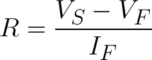
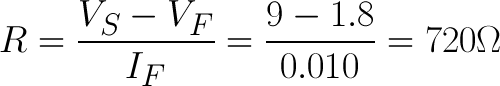
Once you've gotten ahold of those two values, you can size up a current-limiting resistor with this equation:
VS is the source voltage – usually a battery or power supply voltage. VF and IF are the LED's forward voltage and the desired current that runs through it.
For example, assume you have a 9V battery to power an LED. If your LED is red, it might have a forward voltage of around 1.8V. If you want to limit the current to 10mA, use a series resistor of about 720Ω.
Voltage DividersA voltage divider is a resistor circuit which turns a large voltage into a smaller one. Using just two resistors in series, an output voltage that's a fraction of the input voltage can be created.
Here's the voltage divider circuit:
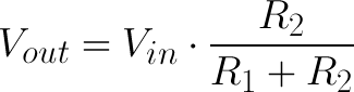
Two resistors, R1 and R2, are connected in series, and a voltage source (Vin) is connected across them. The voltage from Vout to GND can be calculated as follows:
For example, if R1 was 1.7kΩ and R2 was 3.3kΩ, a 5V input voltage could be turned into 3.3V at the Vout terminal.
Voltage dividers are very handy for reading resistive sensors, like photocells, flex sensors, and force-sensitive resistors. One-half of the voltage divider is the sensor, and the part is a static resistor. The output voltage between the two components is connected to an analogue-to-digital converter on a microcontroller (MCU) to read the sensor's value.
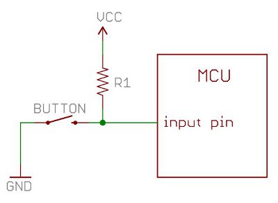
Here a resistor R1 and a photocell create a voltage divider to create a variable voltage output. Pull-up ResistorsA pull-up resistor is used when you need to bias a microcontroller's input pin to a known state. One end of the resistor is connected to the MCU's pin, and the other end is connected to a high voltage (usually 5V or 3.3V). Without a pull-up resistor, inputs on the MCU could be left floating. There's no guarantee that a floating pin is either high (5V) or low (0V). Pull-up resistors are often used when interfacing with a button or switch input. The pull-up resistor can bias the input pin when the switch is open. And it will protect the circuit from a short when the switch is closed.
In the circuit above, when the switch is open, the MCU's input pin is connected through the resistor to 5V. When the switch closes, the input pin is connected directly to GND.
The value of a pull-up resistor doesn't usually need to be anything specific. But it should be high enough that not too much power is lost if 5V or so is applied across it. Usually, values around 10kΩ work well.
|


www.bennypass.it

+(39) 347 051 5328
Italy - Kazakhstan


09.00am to 18.00pm
About
We offer the best and economical solutions, backed by 27+ years of experience and international standards knowledge, echnological changes, and industrial systems.
Our Services
Marketing Materials


Marketing Materials1


