
|
UART Serial Communication Protocol In this tutorial, we’ll be discussing our first serial communication protocol (UART). You’ll get to know what is the UART serial communication protocol? How does it work? What are the typical applications for UART? We’ll also discuss in detail the process of creating the required firmware to drive the UART module in our PIC Microcontrollers. And finally, create a simple communication application MCU-To-MCU and test it out. It’s going to be a very long read with a massive amount of information, So let’s get started! You may also need to check out the SPI (serial peripheral interface) tutorial. It’s another 10k words long-read kind of gigantic tutorial. Check it out and maybe keep it bookmarked as a guide for future work!
Introduction To Serial Communication In Embedded Systems, Telecommunication, and Data Transmission applications, Serial Communication is known to be the process of sending data one bit at a time (bit-by-bit) sequentially, over the serial bus. It takes a complete clock cycle in order to transfer each bit from an end to the other. Conversely, parallel communication is known to be the process of sending several bits, even bytes, as a whole only in a single clock cycle. However, even if you transfer fewer data per cycle with a serial transmission, you can do it at much higher frequencies which results in higher net transfer rates than of the parallel communication.
The Fundamental Concepts There do exist many serial communication protocols, each of which is working in a different way. However, it turns out to be some similarity that they do share in common. Frankly speaking, serial communication protocols have Shift Registers somehow/somewhere in their hardware implementation as the working-horse (core). Shift registers are used to shift out the data to be transmitted bit-by-bit each clock cycle. So, let’s dig deeper into a shift register in order to build-up a complete understanding for what is actually happening at the Register(low)-Level. Shift registers are basically some D-Flip-Flops serially connected while sharing the same clock line. Here is a graphical animation that demonstrates how does a shift register work internally.
As you might have noticed, the data input (0’s and 1’s) is being shifted from the input pin to the output end at bit-0. It takes only 1-clock to transfer a single bit, which means it takes 8-clocks for a single byte transfer. For the same of simplicity, we’ll represent the shift register as a single block instead of a series of D-Flip-Flops as shown above.
Here is an animation for an 8-Bit shift register with a serial input & serial output data lines.
Well, now you should know how shift registers are actually working. Frankly speaking, serial communication is as simple as connecting a couple of shift registers together! Connecting the data output of a shift register to be the data input of the other shift register enables us of sending digital data serially from an end to another! In the following animation, I’m connecting a couple of 4-Bit shift registers. One at the transmitter device and the other at the receiver device. The serial bus consists of a couple of wires (data, and clock). Each clock, a bit is sent from the transmitter TX pin and received by the receiver’s RX pin.
As you might have noticed, it takes 4-clocks to send the 4-Bit data from the transmitter to the receiver. This is simply the short answer to the “How Serial Communication Works?”. However, it’s not everything you should know about serial communication or at least to the level of being able to implement a simple serial data transfer process. In fact, there are some other options and configurations for each serial communication protocols. Which includes, various data transmission rates, error detection, and correction mechanisms, and much more that adds to the overall complexity associated with each protocol. We’ll be working with the UART protocol in this tutorial, which has a decent steep learning curve.
Serial VS Parallel Communication As we’ve stated earlier, serial communication is the process of sending data each bit at a time (bit-by-bit). And conversely, the parallel communication is the process of sending multiple bits, even bytes, as a whole in a single clock cycle. A very basic implementation, that you can create on your own, for the parallel data transfer is shown down below. As I’m connecting a couple of 4-Bit registers, via the 5-wire parallel bus (4-data pins + 1-clock). Here is an animation that shows you how parallel data transfer is done.
As you might have noticed, it takes only 1-clock to transfer the data from a transmitter device to the receiver! Frankly speaking, we can theoretically transfer any number of bits (or bytes) using parallel communication protocols in a single clock cycle at a time. Here is a brief comparison between serial communication and parallel communication protocols.
Applications Of Serial Communication Protocols There are countless situations in which we do use one or more of the serial communication protocols. Here, I’ll try to categorize the main purposes for which we use serial communication instead of listing down all possible applications that may be serving the same purposes. Hence, any application will, hopefully, possibly fall under the umbrella of the following purposes.
Serial communication protocols are of fundamental importance for each embedded systems application. And as embedded systems engineers, we must have a very solid experience with almost all of the commonly used serial communication protocols. And in the next sub-section, we’ll see a brief collection of the commonly available serial communication protocols in the embedded market.
Examples Of Serial Communication Protocols There are many serial communication protocols that are existent and being used in various domains and sub-domains of embedded systems. Some of which are more likely to be used in the automotive industry such as LIN & CAN, some of which is more likely to be used for external memory interfacing as I2C, high-speed computer interfacing as USB, and for audio applications such as I2S. Here is a list of the most common serial communication protocols in the industry.
We’ll be focusing only on the UART serial protocol in the rest of this tutorial. Just to understand the fundamentals & mechanics of UART communication. Only then, we’ll be able to develop the necessary firmware in order to transmit data from an embedded MCU to another as we’ll be doing the lab at the end of this tutorial. So, let’s get started with UART!
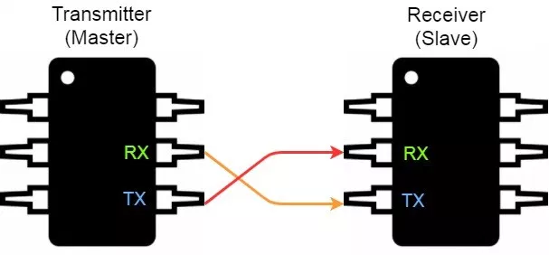
Introduction To UART Universal Asynchronous Receiver/Transmitter or UART for short represents the hardware circuitry (module) being used for the serial communication. UART is sold/shipped as a standalone integrated circuit (IC) or as an internal module within microcontrollers. In this tutorial, we’re actually concerned with the internal UART module within PIC Microcontrollers. There is a couple of io pins dedicated to the UART serial communication module highlighted in the following figure. Namely, RX (data input – receiving end) & TX (data output – transmitting end).
Forms Of UART Communication There are actually two forms of UART as follows:
The Synchronous type of transmitters generates the data clock and sends it to the receiver which works accordingly in a synchronized manner. On the other hand, the Asynchronous type of transmitter generates the data clock internally. There is no incoming serial clock signal, so in order to achieve proper communication between the two ends, both of them must be using the same baud rate. The baud rate is the rate at which bits are being sent bps (bits per second).
So, is UART and USART are the same? Technically, NO! A USART generally has much more capabilities than a generic UART. Being able to generate clocked data allows the USART to operate at much higher baud rates way more than what a typical UART can handle.
Modes Of UART Communication The communication over the UART bus can be configured (set) to be on one of the following modes:
Modes Of Operation For UART Devices The UART serial communication bus can only have 2 devices communicating with each other in one of the 3 modes shown in the previous sub-section. Which necessarily means, each device can either be a transmitter or a receiver during the data transmission process.
You should know that the transmitter in synchronous mode must generate the serial data clock for the receiver. On the other hand, in asynchronous mode, there is no need to do so. And there can’t be more than 2 devices on the UART serial bus. Otherwise, there will be some issues introduced to the system which you’ll have to work around The proper connection for any 2 devices for UART serial communication goes as follows: the transmitter’s TX goes to the receiver’s RX and the receiver’s TX goes to the transmitter’s RX. Frankly speaking, the 2-wires are basically crossed!
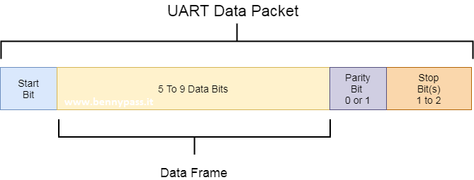
UART Data Packet The data being transmitted/received in UART serial communication is organized into specific blocks called Packets. In the idle state, UART lines are pulled high. This allows the receiver side to recognize that there is a transmitter device on the other end which is connected to the serial bus. UART Packets usually start with “Start Bit” which is a logic low and is used to signal the receiver that there is a new coming packet. The structure of a typical UART Data Packet is shown in the figure down below.
Start Bit The UART data transmission line (TX) is normally held High (1) logic-level when there is no data transmission on the line. To start data transfer, the transmitting UART pulls-down the transmission line from high to low for one clock cycle. When the receiving UART module detects the high to low voltage transition, it begins reading the incoming bits of the entire data frame at the same frequency of the specified baud rate.
Data Frame These are the actual data bits being transmitted from transmitter to receiver. The length of the data frame can be anywhere between 5 and 9 (9-Bits if parity is not used and 8-Bits if parity is used). In general settings, the LSB is the first bit to be shifted-out, transmitted, (unless otherwise specified).
Parity Bit Parity bit allows the receiver to check the correctness of the received data. Parity is a low–level error checking mechanism and has two different options to choose from: Even Parity and Odd Parity. After the receiver UART reads the data frame, it counts the number of bits with a value of 1 and checks if the total value is an even or odd number. If the parity bit is a 0 (even parity), the number of bits with a value of 1 in the data frame should sum-up to an even number. If the parity bit is a 1 (odd parity), the number of bits with a value of 0 in the data frame should sum-up to an odd number. When the parity bit matches the data, the receiver UART knows that the transmission was a success. Frankly speaking, the parity bit is optional and it’s actually not widely used.
Stop Bit As the name suggests, this bit is used to signal the end of the data packet being sent. The sending UART drives the data transmission line from low to high for at least two-bit durations but most often only one bit is used. The data line is held high back to the idle state and ready for any future transmission.
Baud Rate The Baud Rate specifies how fast the data is sent over the bus and it is specified in bits-per-second or bps. You can actually choose any speed for the baud rate. However, there are some specific values that are known to be the industry standards. The most common and widely-used standardized value is 9600. Other standard baud rates include: 1200, 2400, 4800, 19200, 38400, 57600 and 115200. Obviously, baud rates are always multiples of 300. Baud rates higher than 115200(bps) can be used with an additional probability of having, at best, missing data packets. The rule of thumb in UART communication is, both the transmitter and the Receiver UART must agree on the exact same Baud Rate for a successful data transmission.
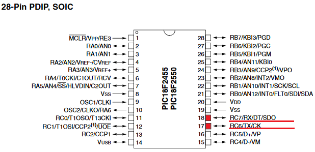
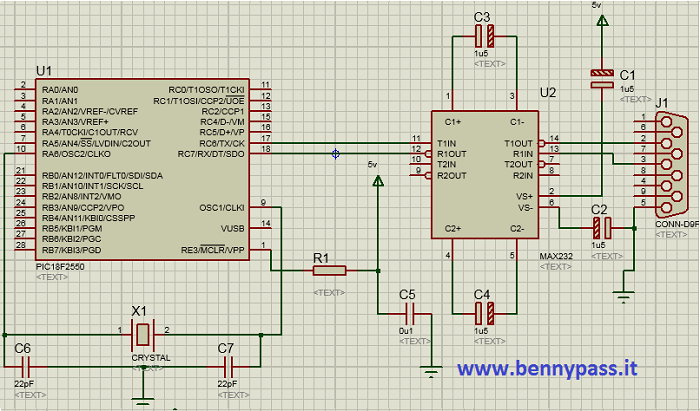
Digital Block Diagram (UART Transmitter) In this tutorial we will try to explain how can configurate a comunication with a simple Microcontroller from Microchip We will use the 28 pin pic18f as per photo below:
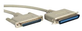
We use the internal EUSART to the PIC Communicating is always the basis of every embedded system. Normally embedded systems use the RS232 or LAN serial port to debug the system during the development phase or communicate with it during the normal execution of an application. The PICs for Debug phase do not normally use the serial port nor the LAN, nevertheless these communication ports play a very important role. In this tutorial we will introduce the serial port and develop some example applications.
Hardware description including all applications Any hardware device after processing a signal in analog or digital mode must be able to communicate the results obtained by means of an output interface. The visualization of the data or further processing can take place by means of another device that can be physically distant from the first, therefore the problem of data transmission arises. Data to be transmitted are digital. Parallel transmission means the use of several data lines130 (wires) to transmit the information. Consider for example the buses connected to the microprocessor, which allow the exchange of information between the latter and the various peripherals on the motherboard. This type of connection allows particularly high speed. Despite the apparent short distances that separate the microprocessor from the various peripherals, it is necessary to wait a non-zero time so that all the bits that constitute the information to be transmitted arrive at the end of the bus. For this and other reasons the parallel transmission is not used for long distances, even if in reality the maximum distance depends also on the maximum frequency with which the information is to be transmitted. For long distances we tend to use a serial transmission; serial transmission means that the information can travel on a single data line131. This class of transmissions includes the RS232 standard which is managed by means of the internal PIC module named EUSART (Enhanced Universal Synchronous Asynchronous Receiver Transmitter). Normally the module names to manage the RS232 are named USART or UART depending on the options. However, many PICs manage some additional options to improve their use in particular applications, like the letter E that is added. Whether the transmission is parallel or serial it is called simplex, half-duplex and full-duplex transmissions, with these names the type of transmission is further characterized. In particular, there is a simplex transmission when the data travels in a single direction, that is, information is sent without worrying about any response from the receiver. With this type of transmission it is not possible to know if the information has actually reached its destination and also there is no real exchange of information1. A half-duplex transmission is a transmission that can take place in both directions but not simultaneously. The fact that transmission does not have to take place at the same time because due to the presence of one cable only for data transmission, or because the hardware resources do not allow bi-directional communication to be obtained in the same time interval. Finally there is the full-duplex transmission that allows communication in both directions and simultaneously. This does not necessarily mean that two data lines are present, one for transmission and one for reception, in fact with frequency multiplexing used for example in telephony, it is possible to transmit more information simultaneously on a single cable. Two other subgroups of transmissions that can be identified both parallel and serial ones is the set of synchronous and asynchronous transmissions. Synchronous transmission means that a Clock in signal is also transmitted together with the data lines, With synchronous transmissions that having a time base available, it is possible to achieve higher transmission speeds if compared with asynchronous case. Although literally asynchronous means without synchronism, it does not mean that this is not present. With asynchronous case we mean only that synchronism is not transmitted by means of a Clock present on an auxiliary line, the synchronism is always necessary. For sending data there are many types of serial and parallel transmissions, as well each language so that two interlocutors can understand each other, so speak the same language. Each language has a grammatical structure that allows a correct transmission of information. In technical terms we speak of a protocol that understand the set of rules and specifications that transmitter and receiver must have in order to understand them. The various rules mostly translate into settings of the PIC itself. Please note that EUSART and RS232 protocol are two distinct things, in particular the RS232 protocol imposes some mechanical (connector) and electrical rules in order to guarantee a standard on physical layer and also on format of the data. The EUSART module respects the data format that the RS232 protocol requires, but in order to respect the entire protocol it is necessary to add the appropriate connector and above all a level shifter (transceiver) to convert the TTL signals coming out of the PIC into RS232 and vice versa.The same EUSART module could be also used for a RS485 transmission, simply changing the transceiver. The Freedom II development board complies with the RS232 standard so it can be used for direct communication with the PC. For the RS485 standard and its connection to the EUSART module, refer to the Freedom sheet (not FreedomII).
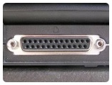
below a photo with configuration between PIC and rs232
For more informations click also rs232 comunication Set up EUSART for proper use As mentioned, the RS232 protocol has many rules regarding the data format, the internal EUSART module respects them and also has features not foreseen by the RS232 protocol. An example is the use of addressing, particularly useful when using RS485 transceivers. This is very useful with these types of transceivers since the RS485 protocol allows multiple peripherals to be connected on the same bus, so the approach of using different addresses for each peripheral is very important. In the case of the RS232 protocol, being designed for peer to peer communication, the concept of address is not very important so it will not be discussed further.
Notice immediately that each function has an x before the final USART word. The x must be changed with the module number inside the PIC. The PIC18 have in fact (depending on the model) up to 3 internal USARTs. In the case of models with only one USART, the x must be removed.
char BusyUSART ( void ) With this function it is possible to check the transmission status of the USART. Parameters: void. Returns: 1: The module is still transmitting the data Example: // Wait for the data transmission to finish while (BusyUSART()); // Continue after transmission
void CloseUSART ( void ) This function closes the previously opened USART module. Parameters: void. Returns: Example: //Close the USART module CloseUSART();
char DataRdyUSART ( void ) With this function it is possible to check whether at least one byte is present in the receive buffer of the USART. If a data is present, the value 1 is returned, otherwise if no data is present, the value 0 is returned. Parameters: void. Returns: 1: The module has a byte in the receive buffer Example: //Wait for data to be received while (!DataRdyUSART()); //Continue after receiving the data
void OpenUSART ( unsigned char config,unsigned int spbrg) Through this function it is possible to open the USART module and set the transmission, reception and possible interruption parameters. To do this you need to fill in the two fields of the OpenUSART function. The first value is given by a bitwise AND of various constants. From the final value the function detects the settings of the internal door. The second value is a register that allows setting the transmission frequency. Parameters: config: The first value of function is set by means of the following constants, joined together by means of AND bitwise &. The constants of interest are: Transmission interruption : USART_TX_INT_ON Interrupt TX ON Interruption in reception: USART_RX_INT_ON Interrupt RX ON USART mode: USART_ASYNCH_MODE Asynchronous mode Data width: USART_EIGHT_BIT 8-bit Slave / Master mode: USART_SYNC_SLAVE Synchronous Slave mode (applies only in synchronous mode) Reception mode: USART_SINGLE_RX Single reception Baud rate: spbrg: The second value that pass to the function is spbrg which allows setting the transmission frequency. This value varies in base on the frequency of the quartz that you are using, and also the whether you are using a high baud rate or not. High baud rate occurs when the BRGH flag is set to 1 while a low baud rate is set with BRGH set to 0. These values are assigned by the OpenUSART function by means of constants USART_BRGH_HIGH and USART_BRGH_LOW. To decide the value of the spbrg variable, you can use the tables shown on the datasheets of the microcontroller that you are using. Table 12 shows the most interesting ones, ie for the asynchronous case high baud rate and low baud rate. The first two tables are refer to the low baud rate option, each column of tables is refers to different quartz frequencies. The last two tables are refer if the high baud rate option is selected, also in this case the columns are refer to the different quartz values. Note: In order to use the EUSART module the following bits must be set as follows:
The EUSART module, when enabled, will set the RC6 bit (TX) of the TRISC register as output. If you use the Microchip library, you don't have to worry about the SPEN bit, the bit will set when the EUSART module opens.
Example: // 20MHz quartz OpenUSART( USART_TX_INT_OFF & USART_RX_INT_OFF & USART_ASYNCH_MODE & USART_EIGHT_BIT & USART_CONT_RX & USART_BRGH_HIGH, 64); Note that to avoid writing all settings on one line, everything was formatted on several lines. For C this is not a problem, since the compiler will look for the semicolon to understand the end of the line. The parameterized AND approach is widely used, normally is implemented by means of an enum structure within, which the constants to be used are defined.
char ReadUSART ( void ) Through this function it is possible to read a byte received from the serial port; the value that read or returned by the function is a type char. Parameters: void. Returns: Example: char data = 0; while (! DataRdyUSART ());
void WriteUSART ( char data ) With this function it is possible to write a data output to the serial port. The data must be of char type therefore of length not superior to 8 bit. Parameters: data: Data to send Returns: void. Example: char data = 0x0A;
For more information on the other functions available in the usart.h library, see the official Microchip documentation. Among the functions not covered in this paragraph but which may be useful. Remember the family of put and get functions that allow write and read single characters or strings, both from variables and from constant strings (rom). For more information on USART settings, see the PIC datasheet used. For more information how can configure the UART with HyperTerminal by using the ASCII code click here.
www.bennypass.it
|
|||||||||||||||||||||||||||||||||||||||||||||||||||||||||||||||||||||||||||||||||||||||||||||||||||||||||||||||||||||||||||||||||||||||||||||||||||||||||||||||||||||||||||||||||||||||||||||||||||||||||||||||||||||||||||||||||||||||||||||||||||||||||||||||||||||||||||||||||||||||||||||||||||||||||||||||||||||||||||||||||||||||||||||||||||||||||||||||||||||||||||||||||||||||||||||||||||||||||||||||||||||||||||||||||||||||||||||||||||||||||||||||||||||||||||||||||||||||||||||||||||||||||||||||||||||||||||||||||

+(39) 347 051 5328
Italy - Kazakhstan


09.00am to 18.00pm
About
We offer the best and economical solutions, backed by 27+ years of experience and international standards knowledge, echnological changes, and industrial systems.
Our Services
Marketing Materials


Marketing Materials1


