
|
I2C module inside the PIC
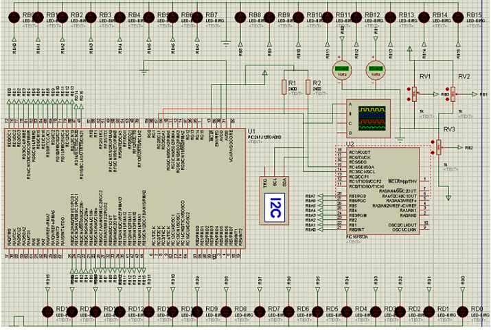
Many microcontrollers including the PIC18 have in addition to the USART, the I2C module that communicates with external peripherals and uses only two wires. In this chapter we will briefly introduce the I2C bus and its applications; then the mode for setting the internal module to PIC18 and PIC24. The Chapter will end with practical examples. The I2C protocol is a standard designed by Philips (now NXP) which owns the property. It was conceived in 1980 to overcome the difficulties inherent in the use of parallel buses for communication between a control unit and the various peripherals. The solutions that are adopted for communication between a microcontroller and external peripherals, generally use parallel communication. For this reason, the bus which the information must travel is made up of many wires. As long as you need to connect a single peripheral to the microcontroller the problems can be uneder conrol, but if the peripherals should be more than one, to getting the bus to each peripheral can be a problem. However, a simple eight-line bus means that each chip has at least many pins to required for communication, which means that dimensions of the chip are dependent on the size of bus. This means that same PCB (Print Circuit Board) which the integrated circuit will be mounted will be larger and therefore more expensive. These problems are entirely overcome by the I2C bus, which allows communication between peripherals with only two lines, this is the reason why it is not uncommon to have a chip with I2C bus with only eight pins. The I2C protocol is a serial standard which, unlike of the RS232 protocol, which allows a point-to-point connection between just two devices, the I2C allows possible to connect a large number of peripherals on the same bus each identified by its own address. The possibility of being able to connect more peripherals on the same bus is also allowed by the RS485 and CAN bus. This last protocol was designed to operate in particularly noisy environments which a particularly high level of data transmission security should be achieved. For these reasons the CAN bus is now accepted as a standard in the automotive sector, that various of electronic devices are increasingly installed on board for the communication. The advantage of devices that use I2C bus is their ease of use. In fact all rules of the protocol that must be respected for a correct communication are managed by hardware level, therefore the designer does not have to worry about anything. Since from born this protocol has been updated in order to adapt it to the different needs that electronics world has requested. All the changes made have always been compatible from top to bottom, meaning the integrated units that meet the latest standards can always communicate with integrated ones of the previous generation. The first version of the I2C bus allows transmitting up to 100Kbit/s (standard mode). This speed was raised to 400Kbit/s in changes made of the 1992 (fast mode). In 1998 the speed was increased to 3.4Mbit/s (high speed mode). It is not necessarily the latest generation of chip devices must comply with the high speed mode. The peripherals that use I2C bus include: EEPROM memories, RAM memories, real-time Clock Calendar, LCDs, digital potentiometers, A / D converters, radio tuners, DTMF tone controllers, generic peripherals to extend the number of inputs or outputs (PCF8574), temperature sensors, audio controllers and much more. Another advantage that allows to obtain the I2C bus is able to add or remove peripherals from the bus without affecting the rest of the circuit. This translates into easy scalability to the top of the system. You can improve a system by adding new features without having to touch the hardware. As mentioned, the I2C bus is a serial bus that requires only two lines called SDA (Serial Data) and SCL (Serial Clock) plus the ground line. Both lines are bidirectional The first is used for the transit of data that are in 8-bit format, while the second is used to transmit the Clock signal necessary for synchronizing the transmission. The I2C bus allows the connection of multiple devices on the same bus but allows communication between only two devices at a time. Being the transmitter or the receiver is not a fixed position, that is a transmitter can also become a receiver in a different phase of data transmission. Not all devices can be Masters of the I2C bus, for example a memory for data maintenance will not be a Master of the bus, while it is reasonable to suppose that a microcontroller can be it On the same bus it is also possible to have more than one Master, but only one at a time will fill this role. If, for example, two microcontrollers start a communication, even if both could potentially be Masters, only one will be, in particular the Master will be the one who started the communication, while the other will be a Slave. Each peripheral inserted in the I2C bus has an address that uniquely identifies it on the bus. This address can be set by the manufacturer during production or partially set by the designer. The address consists of 7 bits in the standard or 10-bit versions in the extended versions. In the case of 7-bit addressing, potentially you can be addressing 128 peripherals, while in the case of 10 bits it is possible addressing up to 1024 peripherals. However, the number of peripherals mentioned above cannot be reached, since some addresses are reserved for special functions. In the case which the address of chip has inside the I2C bus is set by the industry, cannot be connected to the bus with same address. This solution is generally chosen for the Real Time Clock Calendar, or for clocks, it is reasonable to assume that in a circuit in particular on the same bus, there is only one clock that keeps time and date. The use of fixed addresses makes it possible to use reduced packages and optimize the functions offered by the pins. For external memories of the EEPROM type, on the other hand, it is often possible to select the memory address by setting some bits of the address itself (normally 3). It is essential to know that the datasheet of any chip is too important. In order to understanding all the configuration, below a example.We have used a PIC18F873 (slave) and PIC24F128GA010 (master) In order to understand exactly all the configuration, LEDs have been added just for understand the bites that are transmitted. below the photo:
The master is boss of the system, he can calls all slaves by lowering the clock (CLK), sends the address, which can be in writing or reading to the slave, and consequently the slave responds and following the instructions of master. In general step by step how can work:
note: The master can be stop all communication at any time before that slave finish to send all data. He can lower any time the clock line and slave immediately stop all communication. Below a practical routine (in assembly) www.bennypass.it |

+(39) 347 051 5328
Italy - Kazakhstan


09.00am to 18.00pm
About
We offer the best and economical solutions, backed by 27+ years of experience and international standards knowledge, echnological changes, and industrial systems.
Our Services
Marketing Materials


Marketing Materials1


