
Analog Multimeter Working Principle Analog Multimeter
Analog meters are a multifunctional multimeter that operates based on electrical mechanical movement. Analog meters use a printed linear or nonlinear background and a mechanical pointer. The pointer moves as a result of the flow of current through a built-in coil, the presence of electrical pressure, or the internal power source that is needed for resistance measurements. The advantage of an analog meter is relatively small; however, it allows you to see small changes in current flow and a change in voltage in real time. Analog meters require great mathematical skills because you are required to make quick calculations based on the printed scale. Time used while calculating mathematical solutions while taking a reading with an analog meter could be better used to resolve other problems.
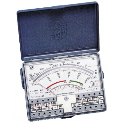
Analyzing from top to bottom on the scale display: The top scale is the ohmic or resistance scale. The pointer needle is past 50 but less than 100. The primary divisions on the scale are 50 and 100. Between 50 and 100, a difference of 50 exists, which represents the secondary divisions. With the five secondary divisions, each of these secondary division indicates 10 to be added to the 50. Each secondary division of 10 contains one subdivision, so each subdivision indicates 5 to be added to the 50. In Figure above, since the pointer is between 50 and the first subdivision and is almost touching the first subdivision, the readout is approximately 54. Now according to the function/range-switch setting, the readout is either 54Ω, 540Ω, or 54 kΩ (54,000Ω).
The Function/Range Switch in an Analog Multimeter If the function/range switch is set on either an AC or DC voltage range, the three voltage scales are analyzed in the same manner. The DC scale is above the three voltage-range scales, whereas the AC scale is below the three voltage-range scales. Both the DC and AC voltage scales contain five primary divisions, with one secondary division and four subdivisions between each primary and secondary division.
Analog Multimeter Scales On the GM Instruments VOM shown in Figure 1, there is only one log scale (nonlinear) for the resistance measurements, although there are three resistance scales indicated on the function/range switch. The three ranges indicated are (R) ´ 1K; (R) ´ 10; and (R) ´ 1. The measured resistance value on the scale readout is the (R) or resistance value that must be multiplied by either 1000 (1K), 10, or 1, according to which resistance range was selected. The DC voltage settings include the 1000-volt scale; the 250-volt scale; the 50-volt scale; and the 10-volt scale. On the scales display, the same 250-volt, 50-volt, and the 10-volt scales are shown double for both AC voltage measures and DC voltage measures. The 10-volt scale doubles for both the 10-volt and the 1000-volt scales: the correct voltage reading is according to the function/range-switch setting. Note: The analog scales on an analog multimeter are normally divided using primary divisions, secondary divisions, and subdivisions. When reading an analog scale, the primary, secondary, and subdivision readings are added to determine the voltage, current, or resistance reading. On the GM Instruments VOM shown in Figure above, a measure is indicated by the pointer located about midway on the scales display. What is being measured is totally dependent on what is not shown in the picture, and that is the selected setting of the function/range switch. Disadvantages The pointer needle is between the 100 and 150 readouts on the 250-volt scale. There are 50 volts between the 100- and 150-volt readouts. The single secondary division in the center between these two readout points divides the 50 volts in half to 25 volts. Between the 100 readouts and the center secondary division, the 25 volts are divided into four 5-volt subdivisions. On the DC voltage scale, the readout appears to be exactly 120 volts. On the AC voltage scale, the pointer needle appears to be about midway between the last subdivision and the center secondary division: the AC voltage readout appears to be about 123 volts. note:A phenomenon referred to as “parallax error” occurs when reading the pointer against the selected scale on an analog multimeter: If you read the scale from a side-angle view, a measured value of 120 volts may appear as 123 volts or 117 volts according to which side of the pointer you are viewing from. The 120-volt reading only occurs when you are looking straight on at the pointer suspended over the scale. The pointer needle is between the 20 and 30 readouts on the 50-volt scale. Ten volts are between the 20- and 30-volt readouts. The single secondary division in the center between these two readout points (20 and 30) divides the 10 volts in half to 5 volts. The four subdivisions between the 20 readouts and the center secondary division divide the 5 volts into 1-volt subdivisions. On the DC voltage scale, the readout appears to be exactly 24 volts. On the AC voltage scale, the pointer needle appears to be about midway between the last subdivision and the center secondary division: the AC voltage readout appears to be about 24.5 volts. The pointer needle is between the 4 and 6 readouts on the 10-volt scale. There are 2 volts between the 4- and 6-volt readouts. The single secondary division in the center between these two readout points divides the 2 volts in half. The four subdivisions between the 4 readouts and the center secondary division divide the 1 volt into 0.2-volt or 2/10ths of a volt subdivision. On the DC voltage scale, the readout appears to be exactly 4.8 volts. On the AC voltage scale, the pointer needle appears to be about midway between the last subdivision and the center secondary division: the AC voltage readout appears to be about 4.9 volts. If the 1000-volt scale is selected, the readout appears to be exactly 480 volts on the DC voltage scale and about 490 volts on the AC voltage scale. Conclusion Due to the many problems associated with an analog multimeter as for as selecting the wrong scales (wrong function setting), especially when the meter is set on an ohmic scale and you are attempting to take a voltage reading, these meters have been known to explode. Handheld analog multimeters have but all been replaced with digital multimeters. According to my experience the analog multimeter remain the best one for measurement of capacitors, transistors, including the diodes, etc. The analog multimeter can indicate some signals that digital multimeter He can not. For example: a transistor is in dispersion and not in short circuit. The analog multimeter can indicate the dispersion to other junction and Digital multimeter no.
www.bennypass.it
|

+(39) 347 051 5328
Italy - Kazakhstan


09.00am to 18.00pm
About
We offer the best and economical solutions, backed by 27+ years of experience and international standards knowledge, echnological changes, and industrial systems.
Our Services
Marketing Materials


Marketing Materials1


