
|
Thyristors: THE TRIAC AND DIAC Introduction Triac is one of the most interesting components of the thyristors family; being able to control the passage of the current in both directions, it represents one of the most efficient and economical solutions for the control of the power absorbed by the users working with alternating voltages.
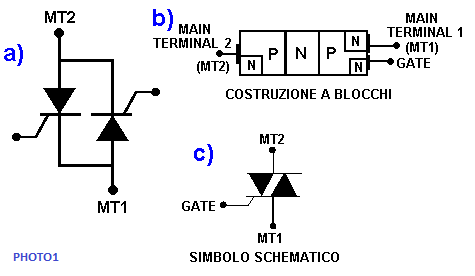
THE TRIAC The triac can be considered as two SCR diodes connected in antiparallel, or side by side, but with opposite directions (scheme a) of figure 1). The anodes of the two SCRs become the main terminals of the triac, and take the name of MT2 and MT1 (Main Terminal 1 and Main Terminal 2). The gates of the two SCRs are connected together, and become the gate of the triac In b) the block construction of a triac is seen, while in c) its schematic symbol is shown.
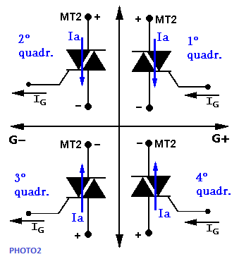
As mentioned above, the TRIAC can be crossed by the current in both directions; it should also be noted that its transition to the "on" state, ie conduction, can occur by applying a positive or negative voltage to the gate. These multiple possibilities of operation can better be illustrated by referring to a graph like that of figure 2, called "four quadrant". Each quadrant represents a different condition of operation of the triac; the polarities and therefore the voltages are always referred to the terminal MT1.
2°: MT2 is always positive compared to MT1, while the gate is negative; the gate current is a current that "goes out" 3°: MT2 is negative compared to MT1, and in fact the current crosses the triac from the bottom to the top; the voltage applied to the gate is negative with respect to MT1 4°: MT2 is negative compared to MT1, while a positive voltage is applied to the gate.
The choice of making Triac work in one quadrant rather than another, or to choose a positive or negative gating voltage, modifies the performance of the device in a more or less important way. Following the physical arrangement of the semiconductor layers that make up the triac, the values of the "latching current" (IL), of the "holding current" (IH) and of the "gate trigger current" (IGT), vary from one quadrant to the other. The most common operation is that corresponding to the 1st and 3rd quadrants, ie when the voltage applied to the gate has the same polarity as that applied to the terminal MT2; in these quadrants an excellent gate sensitivity is obtained. When it is not possible to work in said quadrants, the best alternative is to use the pair of 2nd and 3rd quadrants. Below the table with all characteristic: For convenience and clarity, a table follows that summarizes the main characteristics of thyristors, with the English name and the corresponding meaning in Italian:
The table below gives an example of the values assumed by the current characteristics in the various quadrants, for a 4 A triac.
As can be seen, the gate current is only 10 mA when the triac is made to work in the conditions corresponding to the first quadrant, confirming with this value the best sensitivity; the same current goes to 27 mA for the 4th quadrant, the one with the lowest sensitivity.
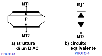
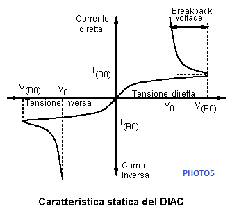
THE DIAC The DIAC is obtained by diffusing type N impurities on both sides of a P-type wafer, so as to obtain a two-terminal device with symmetrical electrical characteristics. The structure of a DIAC is similar to that of an open-base NPN transistor. This is a bidirectional structure, which has a high impedance (and therefore does not let current flow) until the voltage applied to the two terminals does not exceed a certain value, called "breakover voltage". Above this value, the Diac enters a negative resistance zone, where the avalanche conduction effect manifests itself.
As has been mentioned, the passage in conduction of the diac can only take place by overcoming the breakover voltage; in fact, the diac has only two terminals, called anode 1 and anode 2, and therefore does not have a gate.
, www.bennypass.it |

+(39) 347 051 5328
Italy - Kazakhstan


09.00am to 18.00pm
About
We offer the best and economical solutions, backed by 27+ years of experience and international standards knowledge, echnological changes, and industrial systems.
Our Services
Marketing Materials


Marketing Materials1


