
The Transformer working principle
An electrical transformer is a static device which is used for the transformation of AC electrical signal in one circuit to the electrical signal of the same frequency in another circuit with a little loss of power. The voltage in a circuit can be increased or decreased, but with a proportional increase or decrease in the current ratings There are many types of trasformer, below the dettails:
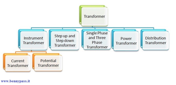
The different types of transformer are Step up and Step down Transformer, Power Transformer, Distribution Transformer, Instrument transformer comprising current and Potential Transformer, Single phase and Three phase transformer, Auto transformer, etc.
Step up and Step down Transformer This type of transformer is categorized on the basis of a number of turns in the primary and secondary windings and the induced emf. Step-up transformer transforms a low voltage, high current AC into a high voltage, low current AC system In this type of transformer the number of turns in the secondary winding is greater than the number of turns in the primary winding. If (V2 > V1) the voltage is raised on the output side and is known as Step-up transformer Step down transformer converts a high primary voltage associated with the low current into a low voltage, high current. With this type of transformer, the number of turns in the primary winding is greater than the number of turns in the secondary winding. If (V2 < V1) the voltage level is lowered on the output side and is known as Step down transformer
Power Transformer The power transformers are used in the transmission networks of higher voltages. The ratings of the power transformer are as follows 400 KV, 200 KV, 110 KV, 66 KV, 33 KV. They are mainly rated above 200 MVA. Mainly installed at the generating stations and transmission substations. They are designed for maximum efficiency of 100%. They are larger in size as compared to the distribution transformer. At a very high voltage, the power cannot be distributed to the consumer directly, so the power is stepped down to the desired level with the help of step-down power transformer. The transformer is not loaded fully hence the core loss takes place for the whole day, but the copper loss is based on the load cycle of the distribution network. If the power transformer is connected in the transmission network, the load fluctuation will be very less as they are not connected at the consumer end directly, but if connected to the distribution network there will be fluctuations in the load. The transformer is loaded for 24 hours at the transmission station, thus, the core and copper loss will occur for the whole day. The power transformer is cost-effective when the power is generated at low voltage levels. If the level of voltage is raised, then the current of the power transformer is reduced, resulting in I2R losses and the voltage regulation is also increased.
Distribution Transformer This type of transformer has lower ratings like 11 KV, 6.6 KV, 3.3 KV, 440 V and 230 V. They are rated less than 200 MVA and used in the distribution network to provide voltage transformation in the power system by stepping down the voltage level where the electrical energy is distributed and utilized at the consumer end. The primary coil of the distribution transformer is wound by enamel coated copper or aluminum wire. A thick ribbon of aluminum and copper is used to make secondary of the transformer which is a high current, low voltage winding. Resin impregnated paper and oil is used for the insulation purpose. The oil in the transformer is used for
The various types of the distribution transformer are categorized on the following basis and are shown in the figure below
The distribution transformer less than 33 KV is used in industries and 440, 220 V is used for the domestic purpose. It is smaller in size, easy to install and has low magnetic losses and is not always loaded fully. As it does not work for constant load throughout 24 hours as in the daytime its load is at its peak, and during the night hours it is very lightly loaded thus the efficiency depends on load cycle and is calculated as All Day Efficiency. The distribution transformers are designed for maximum efficiency of 60 to 70%
Uses of Distribution Transformer
Instrument Transformer
The current and potential transformer is explained below in detail
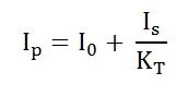
Current Transformer The current transformer is used for measuring and also for the protection. When the current in the circuit is high to apply directly to the measuring instrument, the current transformer is used to transform the high current into the desired value of the current required in the circuit. The primary winding of the current transformer is connected in series to the main supply and the various measuring instruments like ammeter, voltmeter, wattmeter or protective relay coil. They have accurate, current ratio and phase relation to enable the meter accurately on the secondary side. The term ratio has a great significance in CT. For example, if its ratio is 2000:5, it means a CT has an output of 5 Ampere when the input current is 2000 amp on the primary side. The accuracy of the Current Transformer depends upon many factors like Burden, load, temperature, phase change, rating, saturation, etc. In the current transformer, the total primary current is the vector sum of the excitation current and the current equal to the reversal of secondary current multiplied by turn ratio.
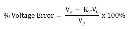
Potential Transformer The potential transformer is also called as the voltage transformer. The primary winding is connected across the High voltage line whose voltage is to be measured, and all the measuring instruments and meters are connected to the secondary side of the transformer. The main function of the Potential transformer is to step down the voltage level to a safe limit or value. The primary winding of the potential transformer is earthed or grounded as a safety point. For example, the voltage ratio primary to secondary is given as 500:120, it means the output voltage is of 120 V when the 500 V is applied to the primary. The different types of potential transformer are shown below in the figure
Optical (works on the electrical property if optical materials)
Single Phase Transformer A single-phase transformer is a static device, works on the principle of Faraday’s law of mutual Induction. At a constant level of frequency and variation of voltage level, the transformer transfers AC power from one circuit to the other circuit. There are two types of windings in the transformer. The winding to which AC supply is given is termed as Primary winding and in the secondary winding, the load is connected.
Three Phase Transformer If the three single-phase transformer is taken and connected together with their all the three primary winding connected to each other as one and all the three secondary windings to each other, forming as one secondary winding, the transformer is said to behave as a three-phase transformer, that means a bank of three single-phase transformer connected together which acts as a three-phase transformer. Three-phase supply is mainly used for electric power generation, transmission and distribution for industrial purpose. It is less costly to assemble three single-phase transformer to form a three-phase transformer than to purchase one single three-phase transformer. The three-phase transformer connection can be done by Star (Wye) and Delta (Mesh) type. The connection of primary and secondary winding can be done by various combinations shown below
The combination of the primary winding and the secondary winding is done as star-star, delta-delta, star-delta and delta-star.
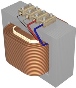
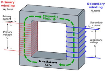
Working of Transformer Let us now shift our attention to our basic requirement: How do transformers work? The operation of transformer mainly works on the principle of mutual inductance between two circuits linked by a common magnetic flux. A transformer is basically used for transformation of electrical energy.
Transformers consist of types of conducting coils as primary winding and secondary windings. The input coil is called the primary winding and the output coil is called the secondary winding of the transformer. There is no electrical connection between the two coils; instead they are linked by an alternating magnetic field created in the soft-iron core of the transformer. The two lines in the middle of the circuit symbol represent the core. Transformers waste very little power so the power out is almost equal to the power in. The primary coil and the secondary coil posses high mutual inductances. If one of the coils is connected to the source of alternating voltage, then an alternating flux will set up in the laminated core. This flux gets linked up with the other coil and an electromagnetic force is induced, as per Faraday’s law of electromagnetic inductance. e = M di/dt Where e is induced EMF M is mutual inductance If the second coil is closed then the current in the coil is transferred from primary coil of the transformer to the secondary coil.
Ideal power equation of transformer While we focus on our query of how do transformers work, the basic we need to know is about the ideal power equation of transformer.
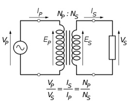
If the secondary coil is attached to a load that allows current to flow in the circuit, electrical power is transmitted from the primary circuit to the secondary circuit. Ideally, the transformer is perfectly efficient; all the incoming energy is transformed from the primary circuit to the magnetic field and into the secondary circuit. If this condition is met, the incoming electric power must equal the outgoing power:
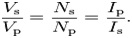
Giving the ideal transformer equation
Transformers normally have high efficiency, so this formula is a reasonable approximation. If the voltage is increased, then the current is decreased by the same factor. The impedance in one circuit is transformed by the square of the turn’s ratio. For example, if impedance Zs is attached across the terminals of the secondary coil, it appears to the primary circuit to have an impedance of (Np/Ns) 2 Zs. This relationship is reciprocal, so that the impedance Zp of the primary circuit appears to the secondary to be (Ns/Np) 2Zp. We hope this article has been brief yet precisely informative about how do transformers work. Here is a simple yet important question for the readers- How is a transformer selected for designing a power supply. For more details click here to see difference between Power transformer and Distribution Transformer
www.bennypass.it
|


+(39) 347 051 5328
Italy - Kazakhstan


09.00am to 18.00pm
About
We offer the best and economical solutions, backed by 27+ years of experience and international standards knowledge, echnological changes, and industrial systems.
Our Services
Marketing Materials


Marketing Materials1


