
The Encoder
Introduction Encoder sensors are a type of mechanical motion sensor that create a digital signal from a motion. It is an electro-mechanical device that provides users (commonly those in a motion control capacity) with information on position, velocity and direction. There are two main types of encoder: linear and rotary. Here, we look at encoder sensors in more depth. Encoder sensors have become a widely used class of sensors where feedback information from a moving mechanical system is required. It is a device that can provide precise information on the speed, direction and positioning of a piece of mechanical equipment. In recent years, encoders have become a lot more sensitive and tough with higher resolutions at a lower cost, and as a result are now widely used in many industries. From an industry perspective, encoder sensors are used across the automotive, consumer electronics, medical, military, manufacturing and scientific instrument industry sectors. In terms of specific applications, encoder sensors can be found in printers, food processing, robotics, material handling, axis controllers, medical scanners, dispensing pumps, military-grade antennas, drilling machines and telescopes, to name but a few.
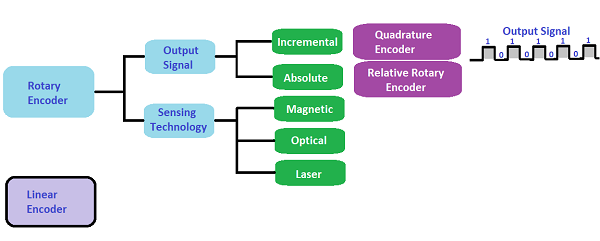
Working Principles The difference between the two different types of encoder is the way in which they respond to motion in a given area, and the clue is in their names. Linear encoder sensors measure a motion along a linear path, whereas a rotary encoder sensor responds to rotational motion. Both types often employ magnetic principles (a magnetic scale or magnetic field) to detect any changes. The sensor will either detect changes in the magnetic field or magnetic position and this provides an output which represents a speed, position or directional change. There are many encoder sensors each with its own functional characteristics. For more details see Figure below Each class of sensor can be further broken down into absolute and incremental sensors. Absolute encoders use a series of pulses to measure the position and speed of the equipment, whereas an absolute encoder uses bit configurations to directly track positions. So, the type of equipment being analyzed, and how it moves, determines what type of encoder sensor is needed. What is the difference between incremental and absolute encoders? What exactly is the difference between incremental and absolute encoders? Both can be used to measure distance, speed, acceleration and position of a mechanical system. The key difference is what happens if that system has a loss of power. After power cycling, incremental encoders are not going to be able to report exact position of the system until they find the index/home position – if they have one. Absolute encoders will be able to report the exact position without returning to a home position after power loss. belo full details: Incremental Encoders
Absolute Encoders
Rotary Incremental Encoder with on / off contacts only
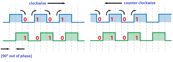
There are many different types of rotary encoders which are classified by either Output Signal or Sensing Technology. The particular rotary encoder that we will use in this tutorial is an incremental rotary encoder and it’s the simplest position sensor to measure rotation. The Incremental Encoder is one of the most popular devices. Practically the is used everywhere, from the robotic to the Oil & Gas, especially used from position transmitters that controlling the control valves where the positioning is crucial. Let’s take a closer look at the encoder and see its working principle. Here’s how the square wave pulses are generated: The encoder has a disk with evenly spaced contact zones that are connected to the common pin C and two other separate contact pins A and B, as illustrated below. When the disk will start rotating step by step, the pins A and B will start making contact with the common pin and the two square wave output signals will be generated accordingly. Any of the two outputs can be used for determining the rotated position if we just count the pulses of the signal. However, if we want to determine the rotation direction as well, we need to consider both signals at the same time. We can notice that the two output signals are displaced at 90 degrees out of phase from each other. If the encoder is rotating clockwise the output A will be ahead of output B.
So, if we count the steps each time the signal changes, from High to Low or from Low to High, we can notice at that time the two output signals have opposite values. Vice versa, if the encoder is rotating counter clockwise, the output signals have equal values. So considering this, we can easily program our controller to read the encoder position and the rotation direction.
Rotary Incremental Encoder of Magnetic Principle and Proximity sensor method
Magnetic Encoder
Magnetic encoders use a combination of permanent magnets and magnetic sensors to detect movement and position. A typical construction uses magnets placed around the edge of a rotor disc attached to a shaft and positioned so the sensor detects changes in the magnetic field as the alternating poles of the magnet pass over it. The simplest configuration would have a single magnet, with its north and south poles on opposite edges of the rotor, and a single sensor. Such a device would produce a sine wave output with a frequency equal to the rotational speed of the shaft. The Magnetic Encoder with a single sensor is most used for read the speed of an electrical generator. The generator can go a direction only With a second sensor, set 90° apart from the first and therefore generating a cosine output, it becomes possible to not only detect the direction of rotation but also to interpolate the absolute position of the shaft from the sine and cosine signals (Fig. 1). For incremental encoders, the sinusoidal outputs from the sensors are converted to square waves so the resulting quadrature waveforms can only be encoded to one of four possible angular positions. Greater resolution is achieved by increasing the number of magnetic poles around the rotor and by having more sensors. For example, 1024 positions (or 10-bit resolution) can be achieved with four sensors and 128 poles. A magnetic rotary encoder comprises two poles and two sensors. The second sensor makes it possible to not only detect the direction of rotation but also to interpolate the absolute position of the shaft. However, this is also a very important sensor Proximity sensor The Proximity sensor is a simple sensor which is applied a gear wheel that counts the protruding parts of wheel (see Figure above side left). More speed increases and more the pulses will increase. The Proximity sensor is used for a lot of application as a axial shaft displacement of a machine, or opening and closing the valves, etc. Clearly, they have different sensitive but its internal functioning remains exactly the same, this is reason why is called Proximity sensor. The Proximity sensor which connected to an electronic bit counters it can detect a speed, a frequency, but cannot detect the position, including the direction. The principle of functionality remains the same, means square wave or binary code 0 - 1, or contact open and contact close,(see photo above left side).
Optical Encoder As with incremental encoders, absolute optical rotaryencoders use a rotating disk to interrupt the light path to aphotodetector, which produces an output signal. However,absolute encoders read uniquely coded tracks to generateposition information. No two adjacent positions are alike.Therefore, absolute encoders do not lose position data whenpower is lost. True position is available as soon as power isrestored. Schematic Representation of an Optical Encoder One Track and One Pick-Off Sensor Shown
Among the most popular position measuring sensors, optical encoders find use in relatively low reliability and low resolution applications. An incremental optical encoder (Figure above) is a disc divided into sectors that are alternately transparent and opaque. A light source is positioned on one side of the disc, and a light sensor on the other side. As the disc rotates, the output from the detector switches alternately on and off, depending on whether the sector appearing between the light source and the detector is transparent or opaque. Thus, the encoder produces a stream of square wave pulses which, when counted, indicate the angular position of the shaft. Available encoder resolutions (the number of opaque and transparent sectors per disc) range from 100 to 65,000, with absolute accuracies approaching 30 arc-seconds (1/43,200 per rotation). Most incremental encoders feature a second light source and sensor at an angle to the main source and sensor, to indicate the direction of rotation. Many encoders also have a third light source and detector to sense a once-per-revolution marker. Without some form of revolution marker, absolute angles are difficult to determine. A potentially serious disadvantage is that incremental encoders require external counters to determine absolute angles within a given rotation. If the power is momentarily shut off, or if the encoder misses a pulse due to noise or a dirty disc, the resulting angular information will be in error. This type of optical can detect the speed but cannot control the direction like the absolute one. In additional also it is not able to find the position after a reset which is the fundamental for a electronic circuit or a position of control valve etc.
Schematic Diagram of an Absolute Encoder Disk Pattern
The absolute optical encoder (see Figure above) overcomes these disadvantages but is more expensive. An absolute optical encoder's disc is divided up into N sectors (N = 5 for example shown), and each sector is further divided radially along its length into opaque and transparent sections, forming a unique N-bit digital word with a maximum count of 2N– 1. The digital word formed radially by each sector increments in value from one sector to the next, usually employing Gray code. Binary coding could be used, but can produce large errors if a single bit is incorrectly interpreted by the sensors. Gray code overcomes this defect: the maximum error produced by an error in any single bit of the Gray code is only 1 LSB after the Gray code is converted into binary code. A set of N light sensors responds to the N-bit digital word which corresponds to the disc's absolute angular position. Industrial optical encoders achieve up to 16-bit resolution, with absolute accuracies that approach the resolution (20 arc seconds). Both absolute and incremental optical encoders, however, may suffer damage in harsh industrial environments.
Advantages and applications of optical encoder The optical encoder has the advantage that it is easy to improve accuracy and resolution by devising the shape of the slit becasue it has a mechanism that detects whether light passes through the slit or not. Therefore, it is used for servo control and hollow through shaft type motor control that require high precision. In addition, since it is not affected by the surrounding magnetic field, it can be used in applications where a strong magnetic field is generated. Therefore, it is used in devices that use large-diameter motors.
Linear Encoders Indroduction In a linear encoder a magnetic sensor passing over a magnetic scale. As the sensor moves along this scale, it detects changes in the magnetic field which are proportional to the measuring speed and the displacement of the sensor. As linear sensors only detect changes in the magnetic field, external factors such as light, debris or oil have no effect on the sensing capabilities, and as a result they are often used in harsher environments. Optical linear encoders are not as widely used, but use parallel beams of light on a glass scale to generate sinusoidal wave outputs that are detected using a photodetector. There are many key components to linear encoder sensors, including the scanning unit, sensor unit, transducer and a transmissive/reflective scale. Overall, the linear encoder converts the motion into either a digital or analog signal and this can be used to determine the positional change over time. Working Principles
A linear encoder is a sensor, transducer or reading-head linked to a scale that encodes position. The sensor reads the scale and converts position into an analog or digital signal that is transformed into a digital readout. Movement is determined from changes in position with time. Both optical and magnetic linear encoder types function using this type of method. However, it is their physical properties which make them different. Linear encoder is used on conveyor belts in factories, or assembly lines, and also on printers to move ink from one side of sheet to another. Both sensors are very reliable but the optical one doesn't get along with dirt, this is reason the magnetic is more reliable Optical Linear Encoders The light source and lens produce a parallel beam of light which pass through four windows of the scanning reticle. The four scanning windows are shifted 90 degrees apart. The light then passes through the glass scale and is detected by photosensors. The scale then transforms the detected light beam when the scanning unit moves. The detection of the light by the photosensor produces sinusoidal wave outputs. The linear encoder system then combines the shifted signals to create two sinusoidal outputs which are symmetrical but 90 degrees out of phase from each other. A reference signal is created when a fifth pattern on the scanning reticle becomes aligned with an identical pattern on the scale. Magnetic Linear Encoder A Linear Encoder system uses a magnetic sensor readhead and a magnetic scale to produce TTL or analog output for Channel A and B. As the magnetic sensor passes along the magnetic scale, the sensor detects the change in magnetic field and outputs a signal. This output signal frequency is proportional to the measuring speed and the displacement of the sensor. Since a linear encoder detects change in the magnetic field, the interference of light, oil, dust, and debris have no effect on this type of system; therefore they offer high reliability in harsh environments.
www.bennypass.it
|

+(39) 347 051 5328
Italy - Kazakhstan


09.00am to 18.00pm
About
We offer the best and economical solutions, backed by 27+ years of experience and international standards knowledge, echnological changes, and industrial systems.
Our Services
Marketing Materials


Marketing Materials1


