SAE BSPP threaded flanges
Introduction:
SAE flanges are made per SAE J518 / ISO 6162 standards. SAE flanges are used in oil hydraulic systems. SAE flanges are also known as SAE Code 61 Flanges or SAE Code 62 Flanges. Code 61 represents 3000 PSI working pressure, while Code 62 represents 6000 PSI working pressure.
SAE Flanges are available with an O-Ring side, flat side, or a complete set, depending on the hydraulic system requirements. The materials used to fabricate SAE flanges are steel and stainless steel. There are four common types of connection for SAE flanges: socket weld, butt weld, NPT, and BSPP.
Characteristic
SAE BSPP threaded flanges are the SAE threaded flanges with BSPP type thread. As a sub variety, this product followed all the descriptions of SAE threaded flanges. Below all the information:
Size Range:
- 3000 psi standard pressure series: 1/2″ (DN13) to 5″(DN127)
- 6000 psi high pressure series: 1/2″ (DN13) to 2″(50.8mm)
Materials available:
- Carbon steel
- Stainless steel: AISI 304, 316, 316L, 316Ti or corresponding EN/DIN steel grades 1.4301, 1.4401, 1.4404, 1.4571, other steel grades on request.
Working pressure:
- For 3000 psi light duty series: 35 bar to 350 bar, depends on the strength grade of the bolts used and sizes of the SAE flange.
- For 6000 psi heavy duty series: Maximum working pressure can be 400 bar when the bolts used are in grade 10.9, and 350 bar when using grade 8.8 bolts.
note: The actual max. working pressure also depends on the wall thickness and quality of the tubes used, for stainless steel seamless tubes, we recommend our customers use Younglee’s hydraulic tubing for high pressure applications.
The surface for stainless steel SAE threaded flanges is natural, while the carbon steel SAE screw-in flanges can be supplied in surface conditions as:
- Zinc coated (white)
- Yellow Galvanize zinc
- Phosphated (black)
- Nickle plated
- Blank + oiled
- Untreated oxidation
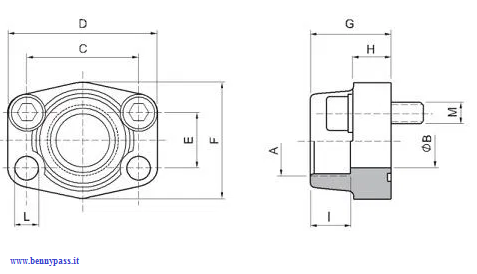
Sizes and data sheet of thread flanges (BSPP)
| Max. working |
Nominal |
Dimensions |
Bolts |
Weight |
Oring |
| pressure |
Flange |
3000 psi standard pressure series / code 61 SAE BSPP thread flanges |
|
Nm |
|
|
|
| kg/cm2 |
Size |
A |
B |
C |
D |
E |
F |
G |
H |
I |
L |
metr. |
Torque |
UNC |
kg |
|
| 350 |
1/2" |
G 1/2" |
13 |
38.1 |
54 |
17.48 |
46 |
36 |
16 |
19 |
9 |
M 8x30 |
32 |
5/16 x 1 1/4" |
0.25 |
4075 |
| 350 |
1/2" |
G 3/8" |
13 |
38.1 |
54 |
17.48 |
46 |
36 |
16 |
19 |
9 |
M 8x30
|
32 |
5/16 x 1 1/4" |
0.28 |
4075 |
| 350 |
3/4" |
G 3/4" |
19 |
47.63 |
65 |
22.23 |
52 |
36 |
18 |
19 |
11 |
M 10x35 |
70 |
3/8 x 1/2" |
0.39 |
4100 |
| 350 |
3/4" |
G 1/2" |
13 |
47.63 |
65 |
22.23 |
52 |
36 |
18 |
19 |
11 |
M 10x35 |
70 |
3/8 x 1/2" |
0.42 |
4100 |
| 315 |
1" |
G 1" |
25 |
52.37 |
70 |
26.19 |
59 |
38 |
18 |
22 |
11 |
M 10x35 |
70 |
3/8 x 1/2" |
0.46 |
4131 |
| 315 |
1" |
G 3/4" |
19 |
52.37 |
70 |
26.19 |
59 |
38 |
18 |
20 |
11 |
M 10x35 |
70 |
3/8 x 1/2" |
0.49 |
4131 |
| 315 |
1" |
G 1/2" |
13 |
52.37 |
70 |
26.19 |
59 |
38 |
18 |
22 |
11 |
M 10x35 |
70 |
3/8 x 1/2" |
0.52 |
4131 |
| 250 |
1.1/4" |
G 1 1/4" |
32 |
58.72 |
79 |
30.18 |
73 |
41 |
21 |
22 |
11.5 |
M 10x40 |
70 |
7/16 x 1 1/2" |
0.66 |
4150 |
| 250 |
1.1/4" |
G 1 1/4" |
32 |
58.72 |
79 |
30.18 |
73 |
41 |
21 |
22 |
13 |
M 12x40 |
70 |
- |
0.66 |
4150 |
| 250 |
1.1/4" |
G 1" |
25 |
58.72 |
81 |
30.18 |
73 |
42 |
25 |
22 |
11.5 |
M 10x40 |
70 |
7/16 x 1 3/4" |
0.75 |
4150 |
| 250 |
1.1/4" |
G 1" |
25 |
58.72 |
81 |
30.18 |
73 |
42 |
25 |
22 |
13 |
M 12x40 |
70 |
- |
0.75 |
4150 |
| 250 |
1.1/4" |
G 3/4" |
19 |
58.72 |
79 |
30.18 |
73 |
41 |
21 |
22 |
11.5 |
M 10x40 |
70 |
7/16 x 1 1/2" |
0.79 |
4150 |
| 200 |
1.1/2" |
G 1 1/2" |
38 |
69.85 |
93 |
35.71 |
83 |
45 |
25 |
24 |
13.5 |
M 12x45 |
130 |
1/2 x 3/4" |
1.05 |
4187 |
| 200 |
1.1/2" |
G 1 1/4" |
32 |
69.85 |
95 |
35.71 |
83 |
45 |
27 |
24 |
13.5 |
M 12x45 |
130 |
1/2 x 3/4" |
1.1 |
4187 |
| 200 |
1.1/2" |
G 1" |
25 |
69.85 |
93 |
35.71 |
83 |
45 |
25 |
24 |
13.5 |
M 12x45 |
130 |
1/2 x 3/4" |
1.16 |
4187 |
| 200 |
1.1/2" |
G 3/4" |
19 |
69.85 |
93 |
35.71 |
83 |
45 |
25 |
24 |
13.5 |
M 12x45 |
130 |
1/2 x 3/4" |
1.23 |
4187 |
| 200 |
2" |
G 2" |
51 |
77.77 |
102 |
42.88 |
97 |
45 |
25 |
30 |
13.5 |
M 12x45 |
130 |
1/2 x 3/4" |
1.19 |
4225 |
| 200 |
2" |
G 1 1/2" |
38 |
77.77 |
102 |
42.88 |
97 |
45 |
25 |
26 |
13.5 |
M 12x45 |
130 |
1/2 x 3/4" |
1.25 |
4225 |
| 200 |
2" |
G 1 1/4" |
32 |
77.77 |
102 |
42.88 |
97 |
45 |
25 |
24 |
13.5 |
M 12x45 |
130 |
1/2 x 3/4" |
1.4 |
4225 |
| 200 |
2" |
G 1" |
25 |
77.77 |
102 |
42.88 |
97 |
45 |
25 |
26 |
13.5 |
M 12x45 |
130 |
1/2 x 3/4" |
1.44 |
4225 |
| 160 |
2.1/2" |
G 2 1/2" |
63 |
88.9 |
114 |
50.8 |
109 |
50 |
25 |
30 |
13.5 |
M 12x45 |
130 |
1/2 x 3/4" |
1.4 |
4275 |
| 160 |
2.1/2" |
G 2" |
51 |
88.9 |
114 |
50.8 |
109 |
50 |
25 |
30 |
13.5 |
M 12x45 |
130 |
1/2 x 3/4" |
1.45 |
4275 |
| 138 |
3" |
G 3" |
73 |
106.38 |
134 |
61.93 |
131 |
50 |
27 |
34 |
17 |
M 16x50 |
295 |
5/8 x 2" |
2.15 |
4337 |
| 138 |
3" |
G 2 1/2" |
63 |
106.38 |
134 |
61.93 |
131 |
50 |
27 |
30 |
17 |
M 16x50 |
295 |
5/8 x 2" |
2.25 |
4337 |
| 35 |
3.1/2" |
G 3 1/2" |
89 |
120.65 |
152 |
69.85 |
140 |
48 |
27 |
34 |
17 |
M 16x50 |
295 |
5/8 x 2" |
2.4 |
4387 |
| 35 |
3.1/2" |
G 3" |
73 |
120.65 |
152 |
69.85 |
140 |
48 |
27 |
34 |
17 |
M 16x50 |
295 |
5/8 x 2" |
2.5 |
4387 |
| 35 |
4" |
G 4" |
99 |
130.18 |
162 |
77.77 |
152 |
48 |
27 |
34 |
17 |
M 16x50 |
295 |
5/8 x 2" |
2.85 |
4437 |
| 35 |
4" |
G 3 1/2" |
89 |
130.18 |
162 |
77.77 |
152 |
48 |
27 |
34 |
17 |
M 16x50 |
295 |
5/8 x 2" |
3 |
4437 |
| 35 |
5" |
G 5" |
120 |
152.4 |
184 |
92.1 |
181 |
50 |
28 |
30 |
17 |
M16x50 |
295 |
5/8 x 2" |
5.8 |
- |
| Max. working | Nominal | Dimensions | Bolts | Weight | |
|---|
| pressure |
Flange |
6000 psi high pressure series / code 62 SAE BSPP thread flanges |
|
Nm |
|
|
|
| kg/cm2 |
Size |
A |
B |
C |
D |
E |
F |
G |
H |
I |
L |
metr. |
Torque |
UNC |
kg |
Oring |
| 400 |
1/2" |
G 1/2" |
13 |
40.49 |
54 |
18.24 |
48 |
36 |
16 |
19 |
9 |
M 8x30 |
32 |
5/16 x1 1/4" |
0.26 |
4075 |
| 400 |
1/2" |
G 3/8" |
13 |
40.49 |
54 |
18.24 |
48 |
36 |
16 |
19 |
9 |
M 8x30 |
32 |
5/16 x1 1/4" |
0.29 |
4075 |
| 400 |
3/4" |
G 3/4" |
19 |
50.8 |
71 |
23.8 |
60 |
35 |
21 |
22 |
11 |
M 10x35 |
60 |
3/8 x1 1/2" |
0.5 |
4100 |
| 400 |
3/4" |
G 1/2" |
13 |
50.8 |
71 |
23.8 |
60 |
35 |
21 |
22 |
11 |
M 10x35 |
60 |
3/8 x1 1/2" |
0.55 |
4100 |
| 400 |
1" |
G 1" |
25 |
57.15 |
81 |
27.76 |
70 |
42 |
25 |
24 |
13 |
M 12x45 |
60 |
7/16 x1 3/4" |
0.76 |
4131 |
| 400 |
1" |
G 3/4" |
19 |
57.15 |
81 |
27.76 |
70 |
42 |
25 |
24 |
13 |
M 12x45 |
60 |
7/16 x1 3/4" |
0.8 |
4131 |
| 400 |
1.1/4" |
G 1 1/4" |
32 |
66.68 |
95 |
31.75 |
78 |
45 |
27 |
25 |
15 |
M 14x45 |
92 |
1/2 x1 3/4" |
1.2 |
4150 |
| 400 |
1.1/4" |
G 1" |
25 |
66.68 |
95 |
31.75 |
78 |
45 |
27 |
25 |
15 |
M 14x45 |
92 |
1/2 x1 3/4" |
1.3 |
4150 |
| 400 |
1.1/2" |
G 1 1/2" |
38 |
79.38 |
112 |
36.5 |
95 |
50 |
30 |
28 |
17 |
M 16x50 |
150 |
5/8 x 2" |
1.65 |
4187 |
| 400 |
1.1/2" |
G 1 1/4" |
32 |
79.38 |
112 |
36.5 |
95 |
50 |
30 |
28 |
17 |
M 16x50 |
150 |
5/8 x 2" |
1.75 |
4187 |
| 400 |
2" |
G 2" |
51 |
96.82 |
134 |
44.45 |
114 |
65 |
37 |
30 |
21 |
M 20x70 |
150 |
3/4 x 2 1/2" |
2.45 |
4225 |
| 400 |
2" |
G 1 1/2" |
38 |
96.82 |
134 |
44.45 |
114 |
65 |
37 |
30 |
21 |
M 20x70 |
150 |
3/4 x 2 1/2" |
2.55 |
4225 |
| 400 |
2.1/2" |
G 2 1/2" |
63 |
123.8 |
180 |
58.8 |
152 |
80 |
45 |
32 |
26 |
M 24x80 |
150 |
- |
6.75 |
4275 |
| 400 |
3" |
G 3" |
73 |
152.4 |
208 |
71.4 |
178 |
90 |
55 |
40 |
33 |
M 30x100 |
295 |
- |
- |
4337 |
Conclusion
SAE Flanges are used for high pressure hydraulic applications. In order to use and assemble SAE Flanges safely, it is important to know the right procedures and torque range for assembly.
Because of the high pressure, it is important to note that every hydraulic or pneumatic system requires some form of fitting installation for completion. Proper fabrication and installation are essential for leak free performance, the overall efficiency, and general appearance of any system.
Assembly of SAE Flanges:
STEP 1 Lubrication SAE Flange
- Ensure the sealed surface are free from scratches and contamination.
- Lubricate with system fluid or any compatible lubricant on the surface of O-ring portion
STEP 2 Threading SAE Flange
- Position the Flange.
- Place the washer on cap screws and bolt through the bolt holes.
STEP 3 SAE Flange Torque Instruction
- Tighten the cap screws by hand.
- Torque the cap screws gradually in diagonal sequence till the appropriate torque level based on below torque table.
STEP 4 SAE Flange Tightening Instruction
- Tighten the cap screws according to the below torque table.
www.bennypass.it
|


