|
SAE split flanges to SAE J518, ISO 6162
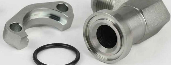
Split SAE flanges are one of the common products of SAE flanges.
Usually two halves (a pair) of SAE split flange halves make up A split flange. There are two main series of SAE split flange halves, which are standard pressure series (3000psi), this series is also known as code 61 SAE split flange, it is also called light duty split sae flange in some areas, It is designed and manufactured according to ISO 6162-1;
and the other series is high pressure series (6000psi) split flanges designed according to ISO 6162-2, this type is also known as code 62 SAE split flange, and it is called heavy duty split sae flange halves in some areas.
Materials of SAE split flange:
- Carbon steel: C20, C45, CQ235, etc.
- ASTM A105, ASTM A182, ASTM A351, ANSI B16.5
- Other materials such as duplex steels on requests
Working pressure:
The working pressure of standard pressure series split SAE flange halves is between 35 bar to 350 bar, depends on the sizes and the blots used. And for 6000 psi high pressure series SAE split flange halves, the working pressure can be up to more than 400 bar.
Advantages of SAE split flange:
The advantage of this type of SAE flange is that the installment on existing piping and hydraulic tubing is easy. SAE split flanges are designed to allow easy installation of the pipes and tubes in tight quarters applications and provide tilt proof clamping.
This simple design provides several advantages over threaded port connections, such as NPT, SAE, BSPP, ISO 6149, etc., in larger sizes:
- Ability to connect up to 5 inch O.D. tube (ISO 6162-1 only)
- Much lower tightening torque required from the four bolts compared to that required for equivalent size threaded port.
- Less tightening torque means smaller wrenches and wrench swing clearances – providing ease of assembly in tight quarters.
- Up to 6000 psi capability through 2" size (ISO 6162-2 only)
- Single seal point between tube/pipe/hose assembly and the port
- Ease of disassembly through use of split clamps
Disadvantage of SAE split flange:
The connection has one disadvantage – it requires a larger area (foot print) on the component than an equivalent threaded port.
Main series & Size range of SAE split flange
Code 61 split flanges (3000 psi standard pressure series): 1/2″ (DN13) to 5″ (DN127)
Below the data sheet of code 61 SAE split flange halves.
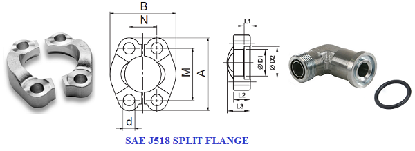
| Size |
A |
B |
d |
M |
N |
D1 |
D2 |
L1 |
L2 |
L3 |
Bolts and Torque Nm +10%
|
Working Pressure Bar |
Oring |
weight kg
|
| DN |
in |
mm |
mm |
mm |
mm |
mm |
mm
|
mm
|
mm |
mm |
mm
|
Nm
|
size x lgth |
CF |
SS |
mm |
x Piece |
| 13 |
1/2”
|
54.0 |
45.6
|
9.0
|
38.1
|
17.5
|
24.3 |
31
|
6.2 |
13
|
19
|
32
|
M8 x 30
|
345
|
345
|
210
|
0.07 |
| 19 |
3/4” |
65.0 |
51.8 |
11.0 |
47.6 |
22.2 |
32.2
|
38.9 |
6.2 |
14 |
22 |
70 |
M10 x 35 |
345 |
345 |
214 |
0.09 |
| 25 |
1” |
70.0 |
58.4 |
11.0 |
52.4 |
26.2 |
38.5 |
45.2 |
7.5 |
16 |
24 |
70 |
M10 x 35 |
345
|
345 |
219 |
0.11 |
| 32 |
1.1/4” |
79.0 |
72.6 |
11.0 |
58.7 |
30.2 |
43.7 |
51.6 |
7.5 |
16 |
22 |
70 |
M10 x 40 |
276
|
276 |
222 |
0.15 |
| 38 |
1.1/2” |
94.0 |
82.2 |
13.5 |
69.9 |
35.7 |
50.8 |
61.1 |
7.5 |
16 |
25 |
130 |
M12 x 45 |
207
|
207 |
225 |
0.23 |
| 51 |
2” |
102.0 |
96.4 |
13.5 |
77.8 |
42.9 |
62.8 |
72.3 |
9.0 |
16 |
26 |
130 |
M12 x 45 |
207
|
207 |
228 |
0.25 |
| 64 |
2.1/2” |
114.0 |
108.2 |
13.5 |
88.9 |
50.8 |
74.9 |
84.9 |
9.0 |
19 |
38 |
130 |
M12 x 45 |
172
|
172 |
232 |
0.37 |
| 76 |
3" |
135.0 |
130.6 |
17.5 |
106.4 |
61.9 |
90.9 |
102.4 |
9.0 |
22 |
41 |
295 |
M16 x 50 |
138
|
138 |
237 |
0.65 |
| 89 |
3.1/2” |
152.0 |
139.2 |
17.5 |
120.7 |
69.9 |
102.4 |
115 |
10.7 |
22 |
28 |
295 |
M16 x 50 |
34
|
34 |
241 |
0.75 |
| 102 |
4” |
162.0 |
151.8 |
17.5 |
130.2 |
77.8 |
115.1 |
127.8 |
10.7 |
25 |
35 |
295 |
M16 x 50 |
34
|
34 |
245 |
0.84 |
| 127 |
5” |
184.2 |
151.8 |
17.5 |
130.2 |
77.8 |
140.5 |
153.2 |
10.7 |
28 |
41 |
295 |
M16 x 50 |
34
|
34 |
253 |
1.25 |
Code 62 split flanges (6000 psi High pressure series): 1/2″(DN13) to 3″(DN76)
Below the data sheet of code 62 SAE split flange halves.
| Size |
A |
B |
d |
M |
N |
D1 |
D2 |
L1 |
L2 |
L3 |
Bolts and Torque Nm +10%
|
Working Pressure Bar |
Oring |
weight kg
|
| DN |
in |
mm |
mm |
mm |
mm |
mm |
mm
|
mm
|
mm |
mm |
mm
|
Nm
|
size x lgth |
CF |
SS |
mm |
x Piece |
| 13 |
1/2”
|
56.0 |
47.2
|
9.0
|
40.5
|
18.2
|
24.6 |
32.5
|
7.2
|
16
|
22
|
32
|
M8 x 30
|
420
|
420
|
210
|
0.08 |
| 19 |
3/4” |
71.0 |
60.0 |
11.0 |
50.8 |
23.8 |
32.5
|
42.0 |
8.3 |
19 |
28 |
60 |
M10 x 35 |
420 |
420 |
214 |
0.18 |
| 25 |
1” |
81.0 |
69.6 |
13.5 |
57.2 |
27.8 |
38.8 |
48.4 |
9.0 |
24 |
33 |
60 |
M12 x 45 |
420
|
420 |
219 |
0.27 |
| 32 |
1.1/4” |
95.0 |
77.2 |
13.5 |
66.6 |
31.8 |
44.5 |
54.8 |
9.8 |
27 |
38 |
92 |
M12 x 45 |
420
|
420 |
222 |
0.27 |
| 38 |
1.1/2” |
113.0 |
95.0 |
17.5 |
79.3 |
36.3 |
51.6 |
64.3 |
12.1 |
30 |
43 |
150 |
M16 x 50 |
420
|
420 |
225 |
0.40 |
| 51 |
2” |
133.0 |
113.8 |
22.0 |
96.8 |
44.5 |
67.6 |
80.2 |
12.1 |
37 |
52 |
150 |
M20 x 65 |
420
|
420 |
228 |
0.40 |
| 64 |
2.1/2” |
175.0 |
150.0 |
25.0 |
123.8 |
58.7 |
90.0 |
108.0 |
20.0 |
45 |
45 |
150 |
M24 x 80 |
420
|
420 |
232 |
0.68 |
| 76 |
3" |
215.0 |
178.0 |
31.5 |
152.4 |
71.4 |
115.0 |
132.5 |
25.0 |
55 |
55 |
295 |
M30 x 90 |
420
|
420 |
237 |
1.05 |
Conclusion
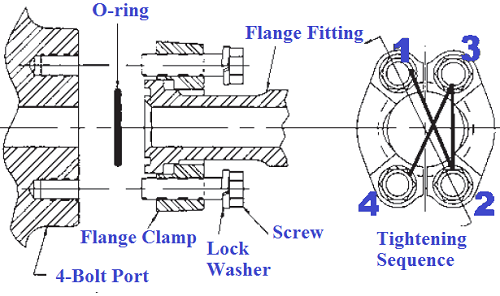
WARNING: It is important that all screws be lightly torqued before applying the final recommended torque values to avoid breaking the split flange clamps or one-piece flange clamps during installation (see Annex A for assembly guidelines).
Recommendation:
- O-ring size code in accordance with ISO 3601-1; see the table above for reference dimensions. wrong o-Ring can damage easy when the split flange will be torqued
- Screw lengths are calculated for steel; use of other materials can require different screw lengths.
- These torque values are only a guide when using lubricated screws, calculated with a coefficient of friction of 0,17. Net tightening torque depends on many factors, including lubrication, coating and surface finish.
- The split flanges as per all others flanges must be tightening in sequence like in the photo below.
www.bennypass.it
|


