
Assembly procedure of the Compression Fittings (A-LOK series)
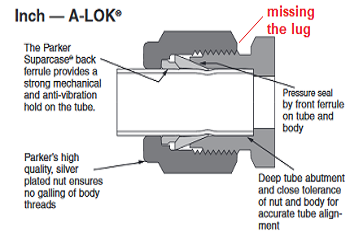
Introduction It has been chosen to use in the guide the company Parker (A-lock series) because it is one of the leading companies in the world. As for all other companies, Parker A-LOK tube fittings are designed to provide reliable leak-free connections for instrumentation, process and control, and analyser applications. Manufactured to the highest quality standards, these tube fittings are available in various sizes, corrosion-resistant materials and multi configurations. As standard, the tube fittings manufacturer’s A-LOK range is manufactured from heat code traceable 316 stainless steel. Other materials include 6Mo, Alloy 825, Alloy 625 and Alloy C-276. Straight fittings are machined from cold-finished bar stock, while shaped bodies are machined from close grain forgings. The tube fittings are available for imperial tube sizes from 1/16” through to 2” O.D. and for metric sizes from 2 mm through to 25 mm O.D. Features and benefits of A-LOK instrumentation tube fittings All Parker A-LOK fittings use an advanced two-ferrule system for reliability and ease of assembly and disassembly. No special tools are required, and the design ensures that all make and remake motion is transmitted axially to the tubing. No radial movement stresses the tubing, so its mechanical integrity is uncompromised. The fittings back ferrule is hardened by Parker innovative Suparcase surface treatment process, which - unlike many competitive hardening processes – actually increases its corrosion resistance. Figure 1 below shows exactly what happens between tubing and ferrule when the gland is screwed into the body of the fitting.
How an A-LOK parker fitting works As can be seen from Figure 1, the tube comes lightly deformed by the ferrule. Practically the ferrules block the exit of the tube from the fitting when it is under pressure.
Assembly procedure Before starting, I want to remind you that A-LOK fittings are provided with two ferrules, back ferrule and front ferrule on the tube and body. Remember, the back ferrule is only for A-LOK fittings. See Figure 2 below.
Figure 2 - Front and Back Ferrules Several companies provide the same technology, but the working principle remains the same; the ferrules bite the tube when the gland of the fitting presses it. Our recommendation for a secure installation is never to install a fitting with different manufacturers inside, such as the ferrule Parker with a gland Swagelok, or different materials, such as ferrule in stainless steel and tube in Inconel. This is not allowed. The connection will not be secure. A fitting must be installed as it is when opening the package.
Tubing preparation
For the tubing cutter, always use the tube cutter as per Figure 3 above. Never use other types of blades like Hacksaws etc. If the saw is used, the tube will be like in Figure 4 below.
The tube preparation process should not begin if the tube is damaged or scratched, as in Figure 5 below.
The cleaning tool
Sometimes, this tool is not used, but in reality, it is essential because it can eliminate any metal chips from the tubing and avoid damaging equipment that the newly built line will supply. The tool includes two sides: one is for cleaning the internal diameter of the tube, and the other is for cleaning the outer part of the tubing. Figure 7 below shows all details (before and after cleaning the tube).
Tube Installation on the Fitting There are 4 Points that absolutely must be followed:
To make it easier, use a marker to highlight (as a reference) some important parts between the tube and the fitting before tightening the gland. Let's see what they are for:
Usually, after tight the gland on the fitting is required to check if the assembly has been carried out correctly. Use the "Inspection Gauge" supplied by Parker to ensure the connection has been made perfectly. Figures 10 and 11 show the special tool provided by Parker.
The working principle is straightforward. Place the gauge between the nut and the body hex. If the gauge does not fit between them, you have correctly tightened the nut. If you can slip the gauge into the space, the fitting is not properly made up, and you must repeat the assembly procedure. Another suitable method is to check if the front ferrule (bigger) inside the tube rotates on the tube without it coming out. This shows that the connection has taken place perfectly. If the ferrule doesn't rotate, extra torque has been applied, which is not required. In this case, a new connection is required. Figure 12 below shows the ferrule installed on the pipe.
Recommendations
|
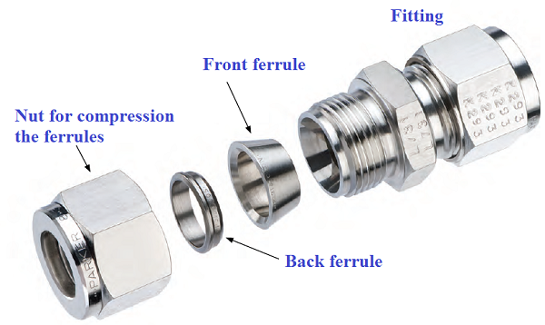
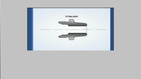
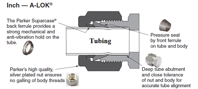
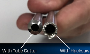
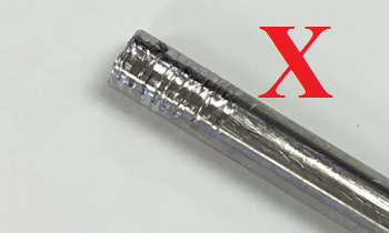
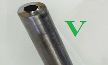
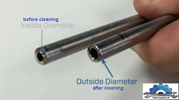
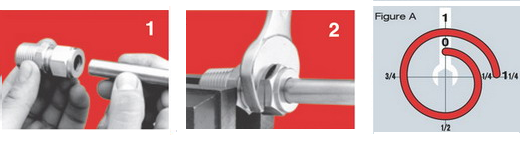
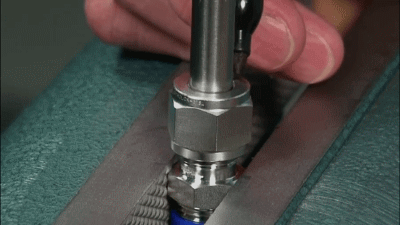
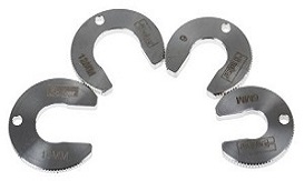 Figure 11 - Inspection Gauge
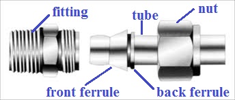


+(39) 347 051 5328
Italy - Kazakhstan


09.00am to 18.00pm
About
We offer the best and economical solutions, backed by 27+ years of experience and international standards knowledge, echnological changes, and industrial systems.
Our Services
Marketing Materials


Marketing Materials1


