Coning and Threading Machine
Introduction
The conical seal fittings are for Ultra High Pressure and can reach pressure up to 150,000 psi (10500 bar). Autoclave Engineers invented this kind of technology over 90 years ago in the United States. The pressure handling capabilities of this connection design have been applied successfully to control pressures up to 150,000 psi. All-metal sealing and working temperatures from 0° to 600°F (-18° to 315°C), along with a variety of different material options, make this connection one of the most versatile ever.
Working principle
Autoclave Engineers (Parker) is the reference in this guide. Many reliable companies provide the same technology, but operation principles remain the same.
Figure 1 Below shows a standard Autoclave Engineers connection
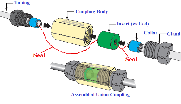 Figure 1 - typical Autoclave connection Figure 1 - typical Autoclave connection
Cone and Thread machine by Autoclave Engineers
Figure 2 below shows an Autoclave Engineers machine which performs the Cone and Thread of tubing together.
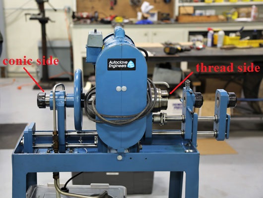 Figure 2 - Autoclave Engineers Machine (115Volts or 220Volts) Figure 2 - Autoclave Engineers Machine (115Volts or 220Volts)
As you can see, the machine is divided into two parts, cone side and thread side, and coupled with a Gearbox and electrical motor. This machine can perform the following tube diameters: 1/4", 5/16", 3/8", 9/16", 3/4", and 1", while the manual hand tool up to 9/16" only (for more details related to the manual tool, click here).
Machine Components
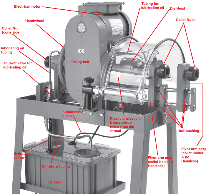 Figure 3 - Machine Components Figure 3 - Machine Components
Note: The Parts mentioned in Figure 3 are those most subject to Wear.
Cone preparation
1st Step: Procedure to assembly the cone tool on the machine
Select the appropriate tools based on the thickness and tube diameter, as shown in the table below.
| Medium Pressure (MP) |
|
Tube Size Inches OD x ID (mm)
|
Collet only
(only 1)
|
Collet only
(set of 3)
|
Cutters only
(Set)
|
Die Chasers
(Set)
|
Complete Set
(all three items)
|
| 1/4” x 0.109 (6.4 x 2.8 mm) |
CTM4C-S |
CTM4C-2 |
CTM4BX |
AEGCTM4D |
AEGCTM4X-2 |
| 3/8” x 0.203 (9.53 x 5.16 mm) |
CTM6C-S |
CTM6C-2 |
CTM6BX |
AEGCTM6D |
AEGCTM6X-2
|
| 9/16” x 0.359 (14.29 x 9.12 mm) |
CTM9C-S |
CTM9C-2 |
CTM9BXX |
AEGCTM9D |
AEGCTM9XX-2 |
| 9/16” x 0.312 (14.29 x 7.92mm) |
CTM9C-S |
CTM9C-2 |
CTM9BX |
AEGCTM9D |
AEGCTM9X-2 |
3/4” x 0.438 (19.05 x 11.13mm)
|
CTM12C-S |
CTM12C-2 |
CTM12B |
AEGCTM12D |
AEGCTM12-2
|
| 3/4” x 0.516 (19.05 x 13.11mm) |
CTM12C-S |
CTM12C-2 |
CTM12BX |
AEGCTM12D |
AEGCTM12X-2
|
| 1” x 0.688 (25.4 x 17.48mm) |
CTM16C-S |
CTM16C-2 |
CTM16BX |
AEGCTM16D |
AEGCTM16X-2 |
| 1” x 0.562 (25.4 x 14.27mm) |
CTM16C-S |
CTM16C-2 |
CTM16B |
AEGCTM16D |
AEGCTM16-2 |
| High Pressure (HP) |
1/4” x 0.083 (6.35 x 2.10mm)
|
CTM4C-S |
CTM4C-2 |
CTM4B |
AEGCTM4D |
AEGCTM4-2 |
| 5/16” x 0.062 (7.94 x 1.57mm) |
CTM5C-S |
CTM5C-2 |
CTM5B |
AEGCTM5D |
AEGCTM5-2 |
| 3/8” x 0.125 (9.53 x 3.18mm) |
CTM6C-S |
CTM6C-2 |
CTM6B |
AEGCTM6D |
AEGCTM6-2 |
| 9/16” x 0.187 (14.29 x 4.78mm) |
CTM9C-S |
CTM9C-2 |
CTM9B |
AEGCTM9D |
AEGCTM9-2 |
9/16” x 0.250 (14.29 x 6.35mm)
|
CTM9C-S |
CTM9C-2 |
CTM9B40 |
AEGCTM9D |
AEGCTM940-2 |
| 1” x 0.438 (25.4 x 11.13mm) |
CTM16C-S |
CTM16C-2 |
CTM16BXX |
AEGCTM16D |
AEGCTM16XX-2 |
| Table 1 |
Everything that you need is shown in the table above. Figure 4,5,6 below shows all three components.
|
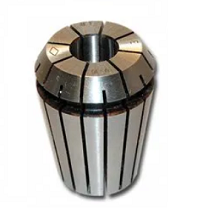 Figure 4 - Collet Tool Figure 4 - Collet Tool
|
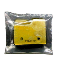 Figure 5 - Cutters Tool Figure 5 - Cutters Tool
|
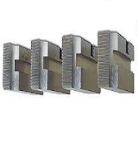 Figure 6 - Die Chasers Figure 6 - Die Chasers
|
These three components are the fundamental parts to make up the cone and thread of the tubing.
Figure 7 below shows the cutter location.
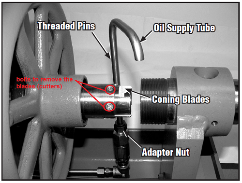 Figure 7 - Cutters Figure 7 - Cutters
To install or replace the cutters, unscrew the bolts from the "holder body" and install the blades. Be careful because the blades have a direction, as shown in figure 8 below (never install in reverse)
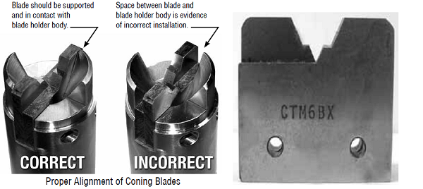 Figure 8 - Cutters Installation Figure 8 - Cutters Installation
Note: When installing new blades, be sure the blades are flat against the holder. There should be no space between the blades and the holder. See Figure 8 above.
Animated Figure 9 below shows the machine ready to use.
 Figure 9 - Cone machine ready to use Figure 9 - Cone machine ready to use
2nd Step: Installation of the Collet
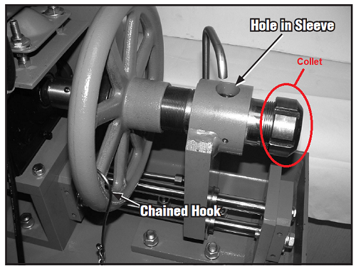 Figure 10 - Collet Nut Figure 10 - Collet Nut
- Determine the appropriate size of the collet by using Table 1 above, including the outside diameter of the tube (OD).
- Remove the collet nut by using the special spanner wrench supplied by Autoclave. Engineers.
- Place the small end of the collet on a hard surface and place the collet nut over the large end of the collet, and push together. They should snap together.
- To separate a collet from the collet nut, grip the collet nut in one hand and pull firmly sideways on the small end of the collet to twist it out of the collet nut.
- Install the collet assembly into the holder.
- Install the collet and collet nuts for the threading end of the machine assembly similarly.
3rd Step: Cone Operation
Recommendations first
- When making the cone on the tube, rotate the handwheel until you see the blade holder in the viewing window (see Figure 10, "Hole in Sleeve). This is the inspection window during the cone performance.
- When the handwheel is not in use and is intended to remain stationary, place the "chained hook" (see Figure 10 above) through spokes to keep the wheel immobile to prevent the holder assembly from contacting the blade assembly.
- Plug the free end of the tubing not being coned or threaded to prevent cutting oil from spilling onto the ground.
- Tubing must be straight for at least 4.75 in. (121 mm) in order to be able to secure the tubing in the collet for coning.
- When cutting a tubing, do not overheat it too much due to losing its strength properties.
Cone execution
Before installing the tube on the machine, make sure the machine is turned off.
- Disengage the chained hook and Rotate the handwheel until the cutting blades extend approximately 1/4" through the hole in the sleeve (see Figure 10).
- With the machine turned off and the power cord unplugged, insert tubing through the collet until it is flush against the blades. Back tubing up about 1/4" and tighten the collet nut with the spanner wrench.
- Connect the power cord and start the machine. Advance the blades by turning the handwheel slowly. When the blades start to cut (as seen through the hole of the sleeve window), rotate the handwheel the number of turns indicated in Table 2 below. Each turn of the handwheel advances the tube 1/16". Advance cutting blades slowly (see note 1).
- After turns of the handwheel are completed (indicated number of turns in table 2), hold the hand wheel stationary for three to five (3-5) revolutions of the cutting blades. This is for cleaning the coned end of the tubing from any cutting residues on the cone (see Note 2).
- Reverse the handwheel until the tubing is disengaged from the cutting blades. Attach the chained hook to the handwheel. If no one is using the threading end of the machine, turn it off.
Note 1: 304 SS tubing will require a slower blade feed rate than 316 SS. The rate of turning the handwheel for 304 SS is approximately 1/4 that of 316 SS.
Note 2: To ensure proper sealing of a coned connection, it is necessary that the finished cone has a square end which is perpendicular to the centre line of the tubing. The critical finish for coned connections is on the leading edge of the cone. The transition point where the cone meets the square end of the tube must be free of burrs and tool marks (See Figure 11 below).
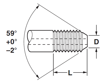 Figure 11 - Tube End Dimensions (see Table 3) Figure 11 - Tube End Dimensions (see Table 3)
| Type of Connection |
Tube Diameters |
Number of handwheel Turns |
| OD in (mm) |
ID in (mm) |
| SM250CX (1/4" MP) |
1/4 (6.4) |
.109 (2.8) |
2.0 |
| SM375CX (3/8" MP) |
3/8 (7.1) |
.209 (5.2) |
2.0 |
| SM562CX20 (9/16" MP) |
9/16 (14.3) |
.312 (7.9) |
2.5 |
| SM562CX10 (9/16" MP) |
9/16 (14.3) |
.359 (9.1) |
2.0 |
| SM750CX20 (3/4" MP) |
3/4 (19.1) |
.438 (11.1) |
3.0 |
| SM750CX10 (3/4" MP) |
3/4 (19.1) |
.516 (13.1) |
2.5 |
| SM1000CX20 (1" MP) |
1 (25.4) |
.562 (14.3) |
4.0 |
| SM1000CX10 (1" MP) |
1 (25.4) |
688 (17.5) |
3.0 |
| M250C / M250C100 (1/4" HP) |
1/4 (6.4) |
.083 (2.1) |
2.0 |
| M312C150 (5/16" HP) |
5/16 (7.9) |
.062 (1.6) |
3.0 |
| M375C / M375C100 (3/8" HP) |
3/8 (7.1) |
.125 (3.2) |
2.5 |
| M562C / M562C100 (9/16" HP) |
9/16 (14.3) |
.188 (4.8) |
4.0 |
| M562C40 (9/16" HP) |
9/16 (14.3) |
.250 (6.4) |
3.5 |
| M562C40-312 (9/16" HP) |
9/16 (14.3) |
.312 (7.92) |
3.5 |
| Table 2 - Reference of the handwheel turns |
Figure 12 - Cone Make-up
Figure 13 - Cone Termination and inspection
Thread Execution
Tools Preparation
Unlike the manual tool, the preparation of the electrical machine to perform the thread on Tubing is totally different. The installation procedure of the Chasers on the Die Head is not elaborate, but some precautions must be considered. One of them is to coincide correctly the numbering of the Chasers with the numbering of the Die Head. Figure 14 below shows this. Never install with a different number between chasers and Die Head.
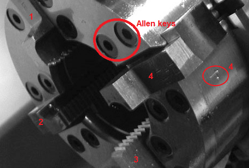 Figure 14 - Die Chasers Assembly Figure 14 - Die Chasers Assembly
Note: The die head has three positions which are: "closed", "open", and "extremely open" position. For Chasers replacement, the die head must be "extremely open".
Assembly procedure of the chasers on the die head
- Stop the machine and remove power from the socket.
- Choose the appropriate tools (collet and chaser). Using Table 1 above and tube size. Install collets as described in Cone Performing guide above (in step two)
- Set the locks on the cart’s wheels to avoid moving the machine during chasers installation
- Move the die head to the extremely open position.
- Almost surely, you may have to start and stop the machine quickly to get the die head to stop spinning in a good position to have access to the head release lever. Turn the machine off and unplug the power cord. Next, press the head release lever (located on the adjusting ring) with an implement, such as a screwdriver, to allow the die head to spring back into the extremely open position (see Figure 15). The die chaser slots should now be fully exposed with the die head in this position.
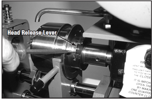 Figure 15 - Head Release lever Figure 15 - Head Release lever
- Remove the bolts with the torque key original from the Autoclave Engineers (see Figure 14 above). Install die chasers on the die head one by one. The chasers and slots are each numbered 1 through 4. The numbered chaser must be placed into the matching numbered slot.
- Make sure blades are clean and free of burrs that could scratch the machine parts. Push chasers into the matching numbered slots until there is a slight click indicating the chaser is seated properly. Chaser spring plungers prevent chasers from falling out.
- As soon as completed, move the die head into the closed position (cutting). Firmly pull trip yoke arms forward, away from the motor, being sure to continue the forward motion after the head release lever snaps into the locking position and until the head locks into the closed (cutting) position.
Recommendations
- Always use the original wrench provided by the manufacturer to remove the bolts on the supports of the chasers. Removing a bolt with a broken head is a big waste of time when it goes right; when it goes wrong, you must replace the entire die head.
- Install the chasers rigorously with the same number indicated between the chasers and the die head.
- When the installation of the chasers is completed, always check if the die head moves correctly in closed (cutting) and vice versa.
- Always check if all four chasers are from the same kit.
- The cover of the slot holder must be fully tightened with the bolts and beat against the die head. In this condition, it could happen that the head does not open automatically when the thread is complete, or instead, it must be helped by hand using the lever (It never has to be like this).
Thread performing
The first thing to do before anything else after the chasers installation is the threads inspection to see if it is configured correctly. With the die head in the closed position, insert a sample nipple (depending on which diameter has been chosen) and check if it screws perfectly in the die head. If it fits badly, maybe the hole is larger or smaller. In this case, unscrew the Ring by using the Allen key, then insert a metal pin tool or rod into the hole in the adjusting ring next to the adjusting ring binding screw and use the tool to rotate the adjusting ring until the desired pitch diameter is obtained. The die head adjusting ring is marked with an “S” (smaller pitch diameter) and an “L” (larger pitch diameter) to indicate the direction to turn the Ring to adjust the pitch diameter smaller or larger (for more details, see Figure 16).
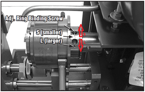 Figure 16 - Thread Adjustment Figure 16 - Thread Adjustment
If the thread matches perfectly proceed to the next step, as shown in Dynamic Figure 17
Figure 17 - Thread performing
- Rotate the tube stop. (Very careful when using the "Tube Stop". The tool is compressed by a spring and fixed with an Allen key. Sometimes, the Allen key can unscrew by itself due to vibrations, with the consequence that the spring escapes quickly from the seat and can injure the personnel near the machine).
- Insert the tubing into the collars nut
- Push the tube until it touches the "Tube stop".
- Screw by hand the two "Collars Nut".
- Lift and rotate the "Tube Stop" in the previous condition (rest)
- With the spanner supplied by the Autoclave Engineers, tighten the "collar nuts".
- Pull towards you the yoke handles to close the "Thread Die Chasers" (Threading Position).
- Push the tube carefully into "Thread Die Chasers" (The tubing must be touching the Die Chasers gently).
- Set the thread length through the tube by "Spacer head assy" (see Figure 18 below). As a spacer, use "the collar of fitting" which will be installed. The collar must overlap between the "Spacer head assy" and "yoke". The distance occupied by the "collar of fitting" will be the thread length of the tube.
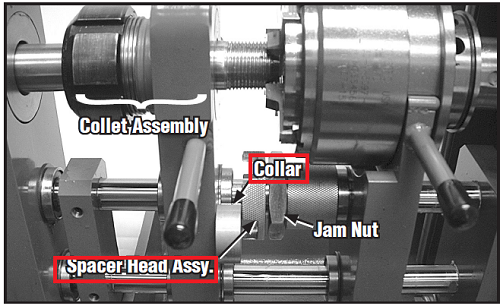 Figure 18 - Spacer head assy (Setting thread length. Die head is shown in the closed position). Figure 18 - Spacer head assy (Setting thread length. Die head is shown in the closed position).
Threading on tube
Figure 19 - Threading Completed
- Turn on the machine and check if the lubricating oil comes out well.
- Push (carefully) the "Inner Yoke" with the tube to the die chasers until they touch each other
- Squeeze the bar handles protruding from each side of the trip yoke and collet assembly toward each other to feed the tube into the chasers until you see the threads being cut. Once all four die chasers are cutting, let go of the handles and the die head will self-feed.
- When the preset length has been threaded, the self-feeding action of the die head will pull the collet and yoke assembly against the spacer head which in turn will push against the trip yoke causing it to open the die head and release the tubing automatically. All this is thanks to the previous calibration between the "Spacer head assy" and "collar".
- Turn off the machine and clean the die chasers.
- Unscrew the collar nuts with the wrench key supplied, then remove the tube.
Cone and Thread Inspection
Figure 20 - Thread and cone inspection
- Screw the collar into the tube (thread just created), as shown in Figure 20 above. Rigorously, the tube thread must exit from the collar at least 1 or 1.5 threads.
- The collar must be screwed by hand without any extra force.
The Tubings
There are several fittings like Autoclave connections, but the working principle is always the same, the seal is metal to metal. The most used lines are with diameters: 1 - 3/4" - 9/16" - 3/8" - 1/4"
Up today, there are no other methods that can withstand high pressure with pipe diameters greater than 1/4 ". For this reason, exists the seal cone-to-cone or metal-to-metal.
When a line is built, the line's rating must include pipe diameter, thickness and materials. Based on these three things will apply the proper fitting (Medium, High, or ultra-high pressure). Click here to see the tables with all details.
Advantages
- The metal-to-metal seal (conic) is a safe system for high and very high pressures.
- Sometimes the internal cone of the fitting gets scratched due to bad installation. There are special tools which possible to repair (it depends on the extent of the scratches) the internal cone without replacing the entire fitting (see Figure 21 below). For each size of fittings and valves, there is a tool. The gland connection can be from 1",3/4",9/16",3/8" 5/16", and 1/4". Based on cone and MP or HP change also the size of the reamer. The same thing is for the tubing cone. The beauty of the cone seal is that possible to Lapping with sandpaper (1200, 2000) like a ball of the valve to remove the scratches from the cone surface (always depends on the extent of the scratches).
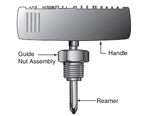
Figure - 21 Reamer Tool
- Existing manual hand tool and electrical machine to perform the Cone and tubing thread (in Auto).
- When performing the thread on the electrical machine, the die head will open the chasers in auto mode to release the threads as soon as complete the cycle (also to prevent thread damage), thanks to the "Spacer head assy", which was calibrated previously through the collar.
- 1/2" TEFC motor, capacitor start.
- The electrical machine is supplied with a reservoir oil and a pump to lubricate (in auto mode) the cone or thread.
- Optional reservoir heater for operation below 65°F.
- Stand mount with locking casters.
- Complete range of tooling available by separate order.
disadvantages
Even if the metal-to-metal seal between fittings and tubing connection is very reliable for high pressure, they also have problems that should not be underestimated. Below the considerations
- All the Parker/autoclave or HIP (or whatever) valves shall be fixed by proper support (mandatory). See Figure 22 below.
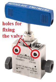
Figure - 22 Autoclave valve
For safety systems, including maintenance, the Autoclave valve must be fixed to support by bolts. The support is mandatory if the valve like in Figure 22 above, is classified as a full seal valve. The problem appears when the valve is closed and under pressure (upstream side only).
Suppose personnel will work on the downstream tubing of the valve, like unscrewing the fitting and removing the tubing from the valve. In that case, there could be a serious possibility that will also unscrew the nut on the upstream valve (just a few mm is enough); therefore, the liquid or gas will exit without any control (under high pressure). This is the reason why the valves need to be fixed. The metal-to-metal seal is very easy to unscrew. Consider also that the Autoclave fitting is straight thread without any seal like NPT, which is conic and requires more power to tighten or unscrew. Unfortunately, there are many sites worldwide without support on the valves, causing several injuries to personnel.
Our suggestion is: Do not try to unscrew or operate (open or close) an autoclave valve under pressure without support.
- The preparation of a line takes several time because every connection must be with maximum accuracy (cone and thread, see procedure above)
- Two keys must be used when tightening a fitting, one to keep the fitting or valve and the other to tighten the nut.
- The fittings must be tightened with the manufacturer's dynamometric key (for all sizes of fittings, there are different torque ranges). See table torque from the autoclave.
- When preparing a connection between the fitting and tube, the tube must be linear with the fitting, the gland must be screwed with the hand till the end, and the last part with the dynamometric key. This procedure shows that the pipe is perfectly linear with the fitting.
- If a fitting opens and closes continuously can easily scratch the cones and cause a leak.
Recommendations
- Never mix components from fitting like collar or gland with other companies.
- Experience does not mean modifying the connection system or internal parts of the fittings but knowing all the procedures written in the manual.
- Those who work on this type of connection must see when the cone or thread they are poorly done and act accordingly by replacing the tool or adjusting the machine.
- You must be very careful to identify fittings or valves with medium or high pressure. The high-pressure surface of the cone exposed to the fluid is smaller than the medium pressure. See Figures 23 and 24 below
|

Figure - 23 High-Pressure Plug
|
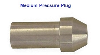
Figure - 24 Medium Pressure Plug
|
- Competent personnel must use this machine. They should understand quickly when the machine gets bad and requires replacing cone or thread tools.
- Never put the fingers or hand inside the machine when it runs.
- Never modify any parts of this machine.
- Always use original tools.
- When working on this machine, always use gloves and protective eyeglasses
- When you operate on the threaded part of the machine, always put the supplied hook on the handwheel to the cone side to avoid rotating the handwheel itself with consequences that can damage the cutter tool or internal gearbox.
Note: If will connect the wrong plug on the valves (mix high pressure with medium pressure), the internal cone will damage, therebefore the only way is to replace the valve.
- FAILURE, IMPROPER SELECTION OR IMPROPER USE OF THE PRODUCTS AND/OR SYSTEMS DESCRIBED HEREIN OR RELATED ITEMS CAN CAUSE DEATH, PERSONAL INJURY AND PROPERTY DAMAGE.Due to the variety of operating conditions and applications for these products or systems, the user, through its own analysis and testing must identified which is the correct fittings,valves,tubings,etc. If you are not sure always please contact qualified people.

|


