
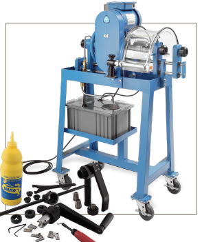
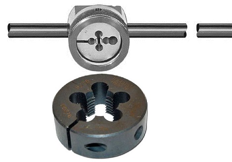
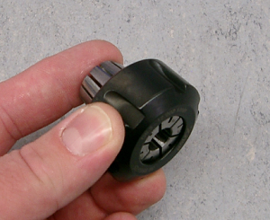
Cone & Thread Manual or Machinery (Special Tools) Introduction In this guide has been taken as reference the Autoclave Engineering company (Parker) Safe, efficient operation of any product is inherently dependent upon its proper installation. In this section the preparation and assembly of low, medium and high pressure connections is explained. Also covered is the assembly procedure for medium and high pressure Cone & Thread Connections as well as anti-vibration collet gland assemblies. There are two type of tools for tubings makeup, manually or by machine see photo below:
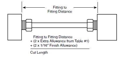
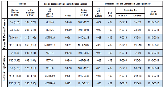
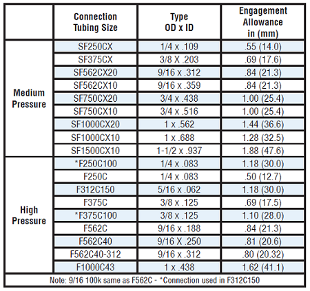
connection type There are a lot of connections type; clearly those more than 9/16 it is not possible with manual tool, see table in Figure 5 The Priority before starting the activity must be identified correctly, which is your tubing ( diameter, thickness, etc) Tubing should be measured accurately and cut to length. Measure the distance from fitting to fitting. See figure 9 for an engagement (assembly) allowance to include in the cut length. Also, an additional 1/16" finish allowance is required per end to square up tube ends. The total cut length will be the sum of the fitting to fitting distance, the engagement allowance and the finish allowances see Figure 9.
Figure 2a assembled tubing
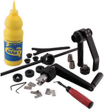
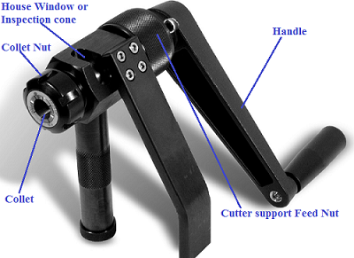
Manual Thread/Conic The hand machine it is similar with electrical one except larger diameters are not included because more force is required and therefore by hand it is not possible. For manual machine the diameters of tubes available are 1/4", 3/8", 9/16". There are two kits, one for medium and the other one for high pressure. Below the photo with all details (only internal parte change, the tool itself is the same for both rating). Figure 3 and 4 below shows the manual tools and Threading tools
Also can be buy a singol componenent as esplaned on the table in figure 5 below
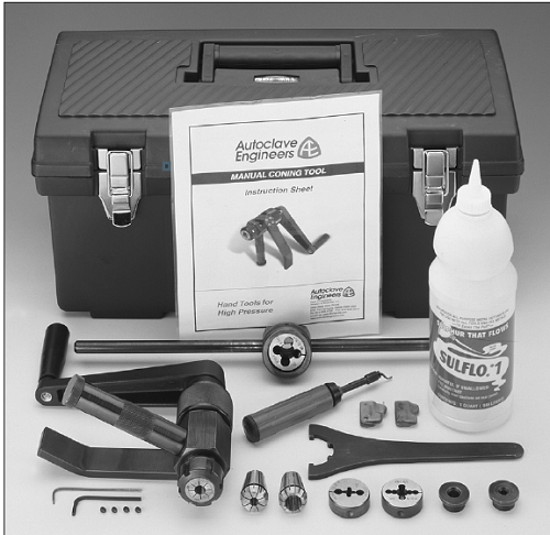
Parker Autoclave Engineers offers coning kits as well as coning and threading tool kits. Each kit consists of the required tools and other items necessary for your coning or coning and threading needs. All kit items are placed in a hand-carry tool case with top tray. The coning tools supplied in the tool kits come complete with the support arm and chip/oil reservoir. Below the datails Medium pressure kit P/N KMCT-MT that include
High pressure kit P/N KMCT-HT that include
With this two part number it's possible to order all what you see in Figure 6 below
Preparation of the Coning tool
Disassembly
Assembly
Preparation of the threading tool
Assembly
Preparation conic on the Tubing Step 1
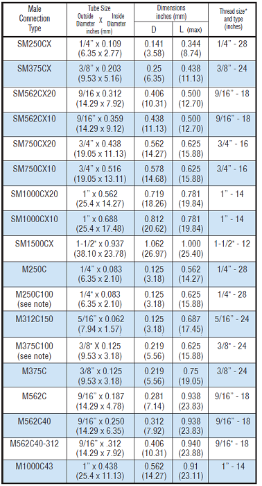
Cut tubing to length and square off the end as close to the required length as possible. Allow extra length for proper engagement into the connection as listed in Table 1 in Figure 8 below.
A small amount of extra length should be allowed to finish the end of the tube, but excessive amounts require additional cutting time and premature blade wear. Note: When cutting tubing with abrasive cut off wheel, tubing should not be over heated effecting material properties.
Step 2
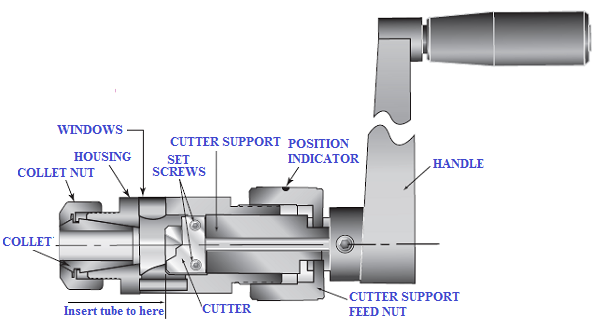
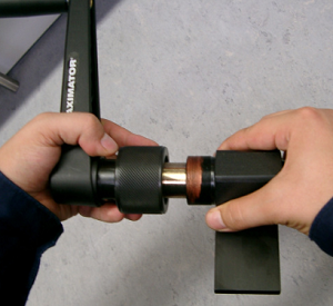
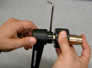
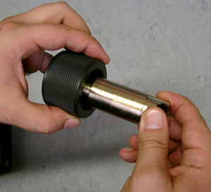
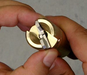
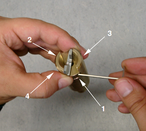
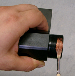
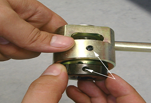
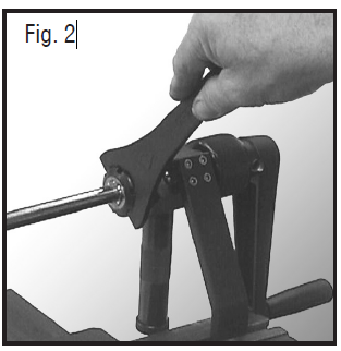
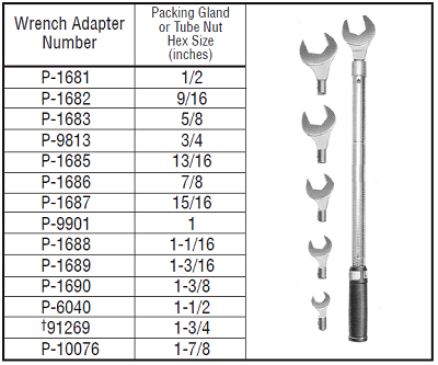
Place the coning tool housing (or optional support arm), without the feed nut/cutter support assembly, in a vise. The vise should be equipped with soft jaws, and the housing should be placed in the vise to allow lubricant to flow to the cutters and cone. Slide the tubing through the collet until the end of the tube appears in the coning tool housing window. Line the end of the tube with the edge of the window and tighten the collet nut firmly in place using the collet nut wrench (see Table 2). In order to protect the collet nut it is better to use the original spanner supplied by Autoclave. Rotate the "Cutter Support Feed" until from the "house window", it is possible to see the cutter touching slow the tubing. A very important thing to avoid damaging the conic blades Step 3
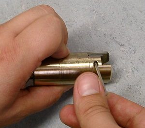
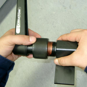
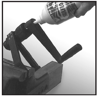
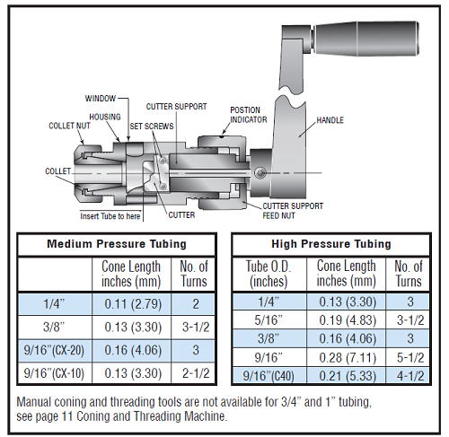
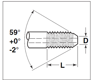
Figure 9 conic blades lubrification Apply cutting oil through the lubricant opening at the end of the cutter holder or directly through the housing window. A medium-weight high sulphur content cutting fluid is recommended. Use the cutting oil freely during the coning operation. The oil avoid to damage easily the conic blades. The distance the feed nut travels from it's start position can be used to gauge the amount of travel to properly cone the tube. The amount of travel is shown in the table in Figure 10 and is labeled “Cone Length”.
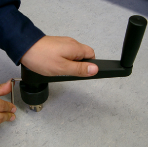
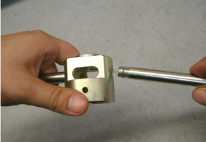
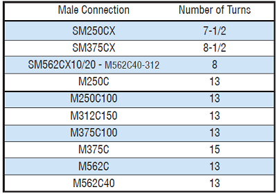
Another method to determine proper cone length is to count the number of turns of the feed nut. The number of turns is listed in Table in Figure 10 under the heading “Number of Turns”. This includes enough advancement of the feed nut to face off the tube. This assumes the tube is cut to length in accordance with these instructions. The feed nut is supplied with a position indicator (drilled hole) to help determine the number of turns. Rotate the handle in a clockwise direction while simultaneously slowly turning the feed nut in a clockwise direction. Rotate the feed nut slowly and evenly to smoothly cone the tube. Loosen collet nut, remove tubing and visually inspect the cone. Use deburring tool to remove any burr on inside edge of tube after coming. The cone must be without any mismatches for all the diameter of the tube.
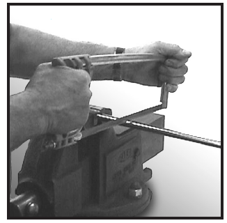
Manual Threading
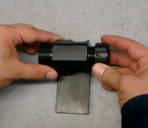
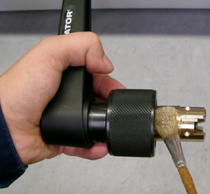
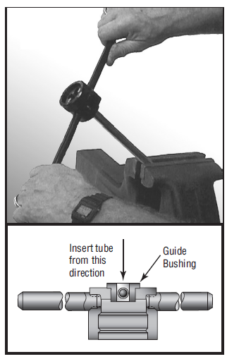
Clamp the tubing in a soft jaw vice. Do not over-tighten. Slide the threading tool over the tube through the guide bushing. Note: Apply a medium-weight, high-sulphur cutting oil to the threading area. Apply pressure to the top of the threading tool to start the cutting action.
Apply pressure to the top of the threading tool to start the cutting action. The threads are left-handed, so turn the threader counterclockwise to thread the tube. The threading tool may need to be periodically rotated clockwise to break and discharge metal chips. Apply lubricant freely during the threading process. Note The lead in chamfer (larger chamfer) on the die flutes toward guide bushing. Continue to rotate the die holder counterclockwise while applying cutting oil generously throughout the process until threads of the following lengths have been cut. See Table in Figure 12 below.
After the tube is coned, threaded and deburred, check for proper thread fit and length with a new collar of the proper size. Note: Remember to flush all tubing prior to installation with a fluid that is compatible with the process fluid being used. Figure 13 below show the number of turn for each size of tubing.
NOTE: M250C100 and M375C100 used in F312C150 connection at 100,000 psi (6895 bar). Make sure before starting that everything is correct. Possibly the first cone and the first thread check if it corresponds to its tolerances. The system confuses ideas, especially when there is the same pipe but with different thicknesses.
Assembly and Makeup of Connection
Recommendations:
Note: The lead in chamfer (larger chamfer) on the die flutes toward guide bushing.
Advantages The comfort of this tool it's really good because all connections can be done on site without electrical power, without any additional transportation, consider also that electrical machine is heavy. The problem if there are many connections, in this case electrical machine is mandatory because only by hands the personel will get tired easily.
Disadvantages If there are many connections,it's better to use the electric machine. The manual tool in long term can cause pain on hands and also arms.
Conclusion
|
||||||||||||||||||||||||||||||||||||||||||||||

+(39) 347 051 5328
Italy - Kazakhstan


09.00am to 18.00pm
About
We offer the best and economical solutions, backed by 27+ years of experience and international standards knowledge, echnological changes, and industrial systems.
Our Services
Marketing Materials


Marketing Materials1


