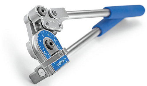
Hand Tube Bender

Introduction

To bend tubes, it’s essential to understand the different processes to bend tubes. Draw, press, ram, and roll bending are the methods that can be considered. Moreover, bending principles such as elongation and bend radius will intersect in several ways that influence the effectiveness of tube bending. Controlling physical deformation is essential for creating a smoothly rounded bend which not affect flow in the tube.

Many companies provide this tool, but two companies are more comfortable, even the others are ok, but in terms of comfort, the "Swagelok" and "Ridgid" are the best.
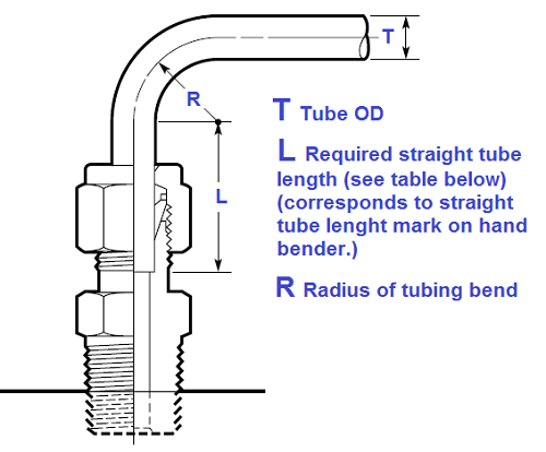


Working Principle

 tubing benderFigure 1 - Swagelok tube bender

The hand tube benders are available 1/8, 1/4, 5/16, 3/8, and 1/2 in., as well as 3, 6, 8, 10, and 12 mm tubing sizes. Clevis handle design provides enhanced leverage for bends greater than 90°. Also, the Roll dies to reduce bending force and tube ovality compared to the conventional slide block design. This tool can perform a bend up to 180° without additional tools.


Tubing Installation

When installing fittings near tube bends, there must be a sufficient length of straight tubing to allow the tube to reach the bottom of the fitting. For more details, see Figure 2 below.

tubing bender connectionFigure 2 - minimum lent of the tube near the Fitting

This is a common and serious mistake during a tubing installation. The personnel does not consider the minimum length required between bend and fitting. This kind of error could be fatal if the line is under high pressure. If will not consider the minimum length required between bend and fitting, the tubing will get stuck in the fitting (deforming), and the ferrule of the fitting cannot be pressed by the nut properly with a risk that under pressure, the tube could come from fitting.

Figure 3 below shows the radius details of the Fractional (Inch) and Metric (mm) tubing.


Fractional, in .

T

Tube OD

R

Bend Radius

L

1/8

9/16

23/32

1/4

9/16

13/16

3/4

5/16

15/16

7/8

3/8

15/16

15/16

1/2

1 1/2

1 3/16

Metric, mm

T

Tube OD

R

Bend Radius

L

3

15

19

6

15

21

8

24

23

10

24

25

12

38

31

 Figure 3 - Tubing Radius reference

 Product Information

tubing bender productionFigure 4 - Production information tube bender Swagelox

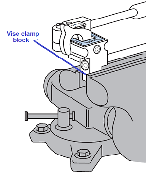
The Swagelok hand tube bender features a vise clamp block which allows the bender to be clamped in a vise. This feature is helpful when the bending tube of a rigid material or heavy wall thickness or long pieces of tubing that need to be supported ( see Figure 5 below).

tubing bender production1Figure 5 - block by vise


This is a good idea especially when the line is long, and the tube thickness is big, including also strong material like Inconel etc.
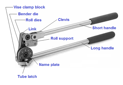
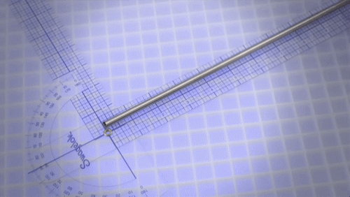
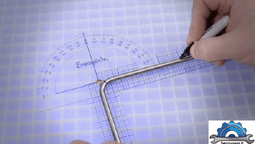
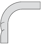
The Measure-Bend Method

Single bend

bent1 Figure 6 - Bending tube procedure

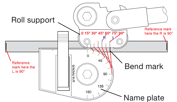
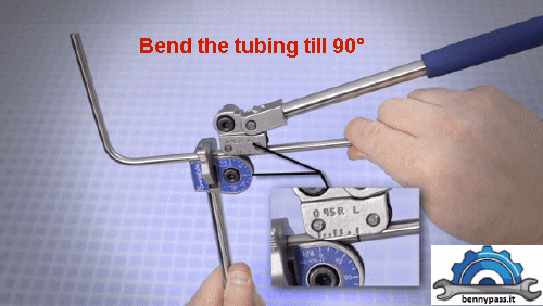
Figure 6 above shows a straightforward 90° bend. Now, let's understand all symbols marked on the bender.

tubing bender1

Figure 7 - Symbols on the tube bender

As you can see, there are two letters, L and R (right and left), so if your reference mark it's located to the left, the bend mark 90° should be L if the reference mark it's located to the right the bend mark 90° should be R. This is the reason why there are R and L.

Double bend 

bent2aFigure 8 - Double bend

Figure 8 above shows a simple double bent of 90°.

Procedure step by step

  • Highlight with a marker where the bend should be performed
  • Apply the second mark that will be the bend direction, in this case, will be the opposite side of the first bent
  • Insert the tubing in the bender with the short handle side on the marks made before
  • Careful low the short handle gently on the tubing
  • Position the tubing perfectly between the mark and L of the bender
  • Position the tubing perfectly parallel with the handle short

Bend tube at 180°

bent3 Figure 9 - 180° tube bender

Procedure step by step

  • Bend the tubing up to 90°
  • Unscrew the short handle and lift till the top beat
  • Screw the short handle
  • Push the short handle and bend the tube until the indication zero of "Roll support" match with indication 180° of "Bender die"

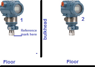
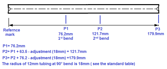
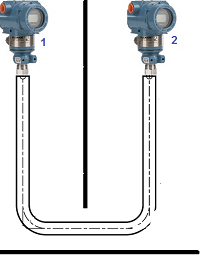
Example

Suppose we need to connect two instruments with a 12m tube (OD) with a 38mm bend radius, but between them, there is a bulkhead that is open only near the floor (see Figure 10 below)

tubing bender4Figure 10 - Connection of two transmitters

Measure the distances between transmitters and the floor, and also the distance between transmitters 1 and 2.

Add all the distances (P1, P2, P3), then prepare a straight tubing with a length approximately to the total of sum P1, P2, P3 plus 5cm more (consider the adjustment radius as per the table below 12mm tubing = 18mm radius).

Mark the tubing as per Figure 11 below

tubing bender3Figure 11 - Tube Marked

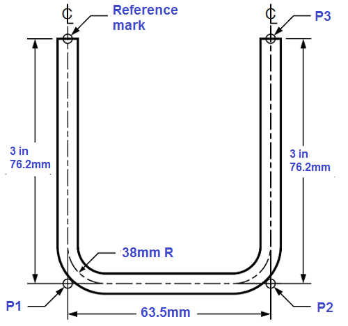
Bend the tube, and the result will be like Figures 12 and 12A below.
tubing bender2Figure 12 - bend result

or this

tubing bender5

Figure 12A - Bend result

The table below shows all bend angle and bend radius details

Fractional Adjustment Calculations


Bend Angle

Tube OD, in .

1/8

1/4

1/4

5/16

3/8

1/2

Bend Radius, in .

9/16

9/16

3/4

15/16

15/16

1 1/2

30°

0

0

0

0

0

1/16

45°

1/16

1/16

1/16

1/16

1/16

1/16

50°

1/16

1/16

1/16

1/16

1/16

1/8

55°

1/16

1/16

1/16

1/8

1/8

1/8

60°

1/16

1/8

1/16

1/8

1/8

3/16

65°

1/8

1/8

1/8

3/16

1/8

1/4

70°

1/8

1/8

1/8

3/16

3/16

5/16

75°

1/8

3/16

3/16

1/4

1/4

3/8

80°

3/16

3/16

3/16

5/16

5/16

7/16

85°

1/4

1/4

1/4

3/8

3/8

9/16

90°

1/4

5/16

5/16

7/16

7/16

11/16

 Metric Adjustment Calculations


Bend Angle

Tube OD, mm

3

6

8

10

12

Bend Radius, mm

15

15

24

24

38

30°

0

1

1

1

1

45°

1

1

2

2

3

50°

1

2

2

2

3

55°

1

2

3

3

4

60°

2

3

3

4

5

65°

2

3

4

4

7

70°

3

4

5

5

8

75°

3

5

6

7

10

80°

4

6

8

8

12

85°

5

7

10

10

15

90°

6

8

12

12

18


Troubleshooting

Tube Bending Defect

Cause

Solution

Wrinkled bend

damage bend

Undersized bend radius

Increase bend radius

Tube wall thickness too thin

Increase wall thickness

Flattened bend

damage bend1

Bender is intended for use with a larger tubing diameter

Use the correct size bender for the tubing being bent

Tubing is collapsing during bending

Increase wall thickness

The pressure die is flattening the tubing during the bending operation

Use a bender equipped with rollers instead of a pressure die

Kinked bend

damage bend2

Bender is intended for use with a larger tubing diameter

Use the correct size bender for the tubing being bent

Premature bending is caused by the link not remaining vertical prior to bending

Make sure the link is vertical before placing rollers on tube

Scored tubing

damage bend3

Bender is intended for use with a smaller tubing diameter

Use the correct size bender for the tubing being bent

Damaged bender die

Repair the bender die or replace the bender

Dirt or foreign matter in bender die/shoe or roller

Clean bender die/ shoe or roller

Frozen roller

Replace damaged roller or bender

Excessive tubing deformation

damage bend4

Improper alignment Make sure that the bender die and bend shoe are aligned
Excessive pressure on the tube latch (generally visible on softer tubing only) Reduce latch pressure


Recommendations

  1. If possible, a goal in tube bending is to eliminate as many connections as possible. The additional connections can cause leaks, which means additional maintenance. Consider where the leaks are critical, like the aircraft, not to mention the additional cost of fittings.
  2. Never use a bender that is smaller or larger than of tubing diameter
  3. This guide more or less is valid for all bending machines on the market. For more information, click here and download the PDF file from Swagelok.
  4. These kinds of tools are provided with two handles, Do not use handle extensions (such as a piece of pipe). The extensions can slip or come off and increase the risk of serious injury; also consider extra power on the bender or different tubing sizes can destroy the entire tool with the consequence that serious injuries can happen to the personnel.


 favicon bac


favicon bacd

+(39) 347 051 5328

Italy - Kazakhstan

09.00am to 18.00pm

About

We offer the best and economical solutions, backed by 27+ years of experience and international standards knowledge, echnological changes, and industrial systems.

Marketing Materials

Spring Renovation
Industry
US Gas Company
Construct
Plus Project
Vam Drilling Service
X Project
X Project
Cabrrus Training

Marketing Materials1

Spring Renovation
Industry
US Gas Company
Construct
Plus Project
Vam Drilling Service
ultrasonic sensor
ultrasonic sensor
Cabrrus Training