|
Smart Positioner
Smart positioners are divided into two categories single effect and double effect, let's to see which is the differences:
Single Effect
Single effect Positioner are the positioner with one pneumatic output only. This type of positioner are installed in the actuators where an spring are installed (see photo below). The spring replace pilot pressure on one side of actuator. Practically one side of spring are pressed by pilot pressure of Positioner, and the other side the actuator returns in condition of rest through the spring. The output of positioner press the spring to open or close valve (fail safe action), can also reduce the output in such way the actuator will moving gradually. This is the reason why is installed a feedback which is connected between actuator and positioner. The feedback read the correct position of actuator and accordingly the positioner icrease or degrase the output to maintain this position (4 - 20mA)
Even if Double effect working with 2 output including sometime an spring , the actuator can working also without spring , the spring is used only for safety reason (fail safe). The single effect cannot work without spring never.
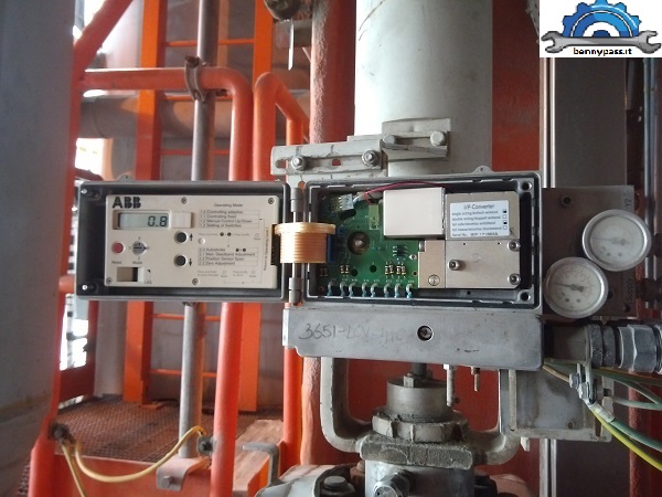
The smart positioner is same with penumatic positioner but in this case is controlled by 4-20mA. Inside it is located a IP Converter that convert the signal from 4 - 20 mA in 3 - 15Psi. Inside there is a booster which amplifies the signal of 3 - 15psi in power supply for pilot the actuator, normally should be around 2 and 4 bar.
The position control or feedback is provided by an encoder connected between positioner and stem valve with an lever. In base of movment of valve stem the encoder rotate. Inside the positioner there is an amplifier that reads the encoder signals and then itself convert the signal in percentage of opening or closing (left or rigth depend from valve)and indicating the correct position of the valve.
below an example of control valve piloted by smart positioner
 In base of model valve there are many positioner transmitters available. The function any way remain more less the same. Normally almost are with auto calibrations and no need any additional calibration except in some cases where his controller (DCS) requires special calibrations (dead band, etc.). Normally the response speed is managed by its controller (DCS) where the PID tuning is performed (Proportional, integral, derivative) Most of the positioners are equipped with the Hart protocol, really very simple. This type of communication slows down the speed execution of positioner, not so much, just a few milliseconds but in some systems such as the antisurge of a compressor these milliseconds are of fundamental importance to protect a compressor. There are also positioners without hart protocol and with other type of communication that directly they interact with its internal program, for example Simens, or ABB which is equipped with his communicator to interact directly with its internal program, or even the software for communicate with laptop (Asset Vision Basic) In base of model valve there are many positioner transmitters available. The function any way remain more less the same. Normally almost are with auto calibrations and no need any additional calibration except in some cases where his controller (DCS) requires special calibrations (dead band, etc.). Normally the response speed is managed by its controller (DCS) where the PID tuning is performed (Proportional, integral, derivative) Most of the positioners are equipped with the Hart protocol, really very simple. This type of communication slows down the speed execution of positioner, not so much, just a few milliseconds but in some systems such as the antisurge of a compressor these milliseconds are of fundamental importance to protect a compressor. There are also positioners without hart protocol and with other type of communication that directly they interact with its internal program, for example Simens, or ABB which is equipped with his communicator to interact directly with its internal program, or even the software for communicate with laptop (Asset Vision Basic)
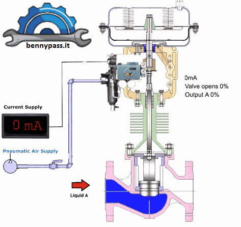
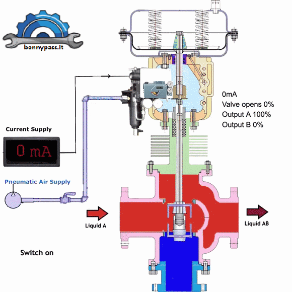
A smart positioner can drive anything that needs adjustment and opening rate, see a damper, or a pneumatic piston. The power supply normally is with 4-20mA to make a run starting from 0 and ending at 100%. The photo below shows how to control a three-way valve with two different liquids, it is controlled by Smart positioner Foxboro SDR 991 single effect
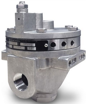
In many cases where the actuators are very big the volume air of positioner are not enough or better the actuator will be moving very slow. For solve this problem existing the volume booster that amplify the air signal from positioner to drive the actuator with big size. The Photo below show an booster from Emerson, one of the very reliable boosters.
Let's see how it works
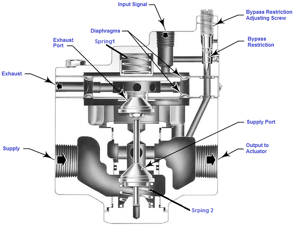
As you can see in the photo above the booster is equipped:
- Direct Air supply
- Out to actuator
- Exhaust port (or release air)
- Input signal from Positioner
- Adjusting screw (sensitive, or fast or slow response)
The booster works exactly like an actuator, exist an diaphragm with a large surface for win the surface of power "Supply" that have a small. This balance is adjustable via the "adjusting screw". When the Positioner will reduce the pressure the spring one and two win and booster open to direction of "Exhaust Port" in this case the valve will open or close depende which fail safe action is implemended.With the bypass restriction adjusted for stable operation, a signal with small magnitude and rate changes passes through the bypass restriction and into the actuator without initiating booster operation.
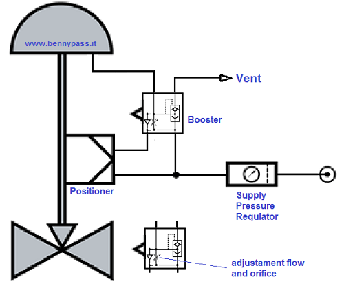
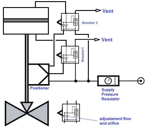
Normally with an actuator equipped with spring, and with a single effect of positioner, one booster is required, but in some case where the valve it is in a critical position should be install two booster, see the photos below with one and two boosters
Drawing with one booster
Drawing with two boosters
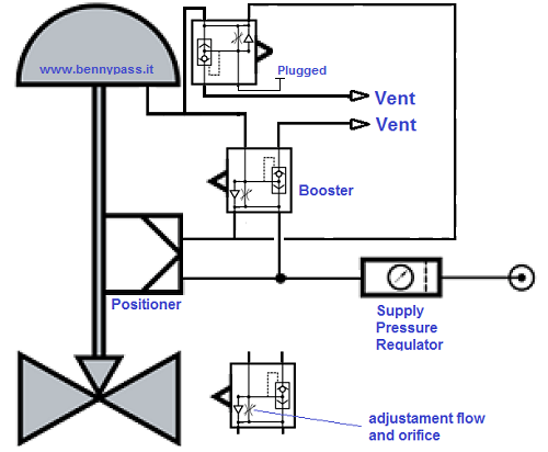
Both supply and exhaust ports remain closed, preventing unnecessary air consumption and possible saturation of positioner relays.
Advantages:
- Quick response with increased actuator stroking speeds
- Maintains correct actuator positioning at high stroking speeds
- Adjustable bypass valve provides good operational sensitivity
- High stability which allow normal slow actuator response to slow signal changes
- Capable of using high pressure plant air supply (maximum working pressure of booster, read datasheet)
- Different Booster sizes available to suit wide range of actuator sizes
Double Effect Positioner
The difference between single effect and double effect of positioner is the double effect is equipped with one more output (output1 and output 2). In double-acting cylinders, the pressure of the compressed air can act in both directions.
The working principle of an double effect actuator it is necessary two power supplies (one by one), one in unloading and one in load and vice versa
The double acting actuator is also used when the application is very high application to overcome the required high thrust even though the size is smaller than 10 inch. This double acting actuator is more stiffer and stable for control application especially for application that has a sudden change in process condition.
In the process control application that use control valve as its final control element, the typical actuator is diaphragm spring return diaphragm for the small valve up to 8 inches. While when it is 10 inch and above the actuator is double acting type to overcome the required high thrust.
While when we use the diaphragm spring return type, the thrust on the other side is always the same by the spring. While when we use the double acting actuator, the other side forces will be managed by the positioner pressure output as per actual conditions.
In double-acting cylinders, the compressed air thrust can act in both directions. These are recommended for large diameters and long strokes. If the cylinder has to move large masses, it is equipped with end-of-stroke shock absorbers to prevent the piston from hitting the end-of-stroke heads.
Double-acting cylinders are used when linear movements are required with the development of forces in both directions.
Below the photo with double effect Actuator and Positioner
Double acting positioner connected to double acting actuators are normally used for large size actuators. You have to pay attention to his work pressure, if the pressure is too high your risk is really big. For example, if the control valve is stacked in an position never increase the air pressure to free the valve, even 1 bar more. Actuators with a big surface 1 bar more is really a big power, and there is a risk can damage actuator and also injury the personal who are near actuator. This is reason why on all actuators are stamp the maximum operating pressure. All actuator double effect e single effect should be following the maximum working pressure specially in the double effect actuators.
Conclusion
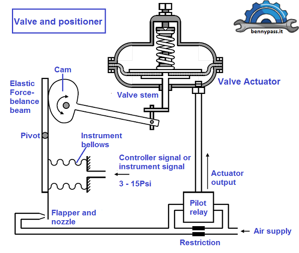
Remember that the purpose of a valve positioner is to ensure the mechanical valve’s position matches the command signal at all times. Thus, a valve positioner is actually a closed-loop control system in its own right: applying as much or as little pressure to the actuator in order to achieve the commanded valve stem position at all times. Mechanical valve positioners use levers, cams, and other physical components to achieve this closed-loop control.
Electronic valve positioners, such as the Fisher or ABB, or Foxboro, etc, use an electronic sensor to detect valve stem position (Encoder), a microprocessor to compare that sensed stem position against the control signal by mathematical subtraction (error = position signal), then a pneumatic signal converter and relay(s) to send air pressure to the valve actuator. A simplified diagram of a generic electronic valve positioner is shown the photo below:
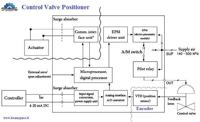
As you can see we have not just one, but two control algorithms working together to maintain proper valve position: one monitoring and controlling pressure applied to the actuator (compensating for changes in air supply pressure that might otherwise affect the valve’s position) and the other monitoring and controlling stem position itself, sending a cascaded control signal to the pressure control components.
The command signal (sent from the process loop controller, PLC, or other control system) tells the positioner where the valve stem should be positioned. The first controller inside the positioner (PI) calculates how much air pressure at the actuator should be needed to achieve the requested stem position. The next controller (PID) drives the I/P (current-to-pressure) converter as much as necessary to achieve that pressure. If anything causes the valve stem to not be at the commanded position, the two controllers inside the positioner work together to force the valve to its proper position.
The electronic valve positioners achieve superior position control when compared to mechanical valve positioners, but their array of sensors and digital communication ability provides a new level of diagnostic data both to maintenance personnel and the supervising control system.
Additionally, the microprocessor embedded within an electronic valve positioner is capable of performing self-tests, self-calibrations, and other routine procedures traditionally performed by instrument technicians on mechanical valve positioners. Having access to such measurements as total valve stem travel even allows an electronic positioner to predictively calculate packing wear-out time, automatically flagging a maintenance alarm notifying operators and/or instrument technicians when the valve’s stem packing will need to be replaced.
The smart positioner can monitor the one of them alarm in the list below and generate a fail
- Low pressure air
- leak air detect on actuator or output positioner
- High Ambient temperature
- position error
- valve stack (not move)
If the microprocessor detects a failed (off-scale) position feedback signal, it may be programmed to continue operating the valve based on pressure alone: adjusting the applied air pressure to the valve actuator according to the pressure/position function it has recorded in the past.
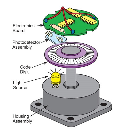
The enconder is like in the photo below:
Article related
How can work the Encoder (philosophy)
How can work the I/P converter (philosophy)
How can work the PID (Proportional Integral Derivative)
Recommendations
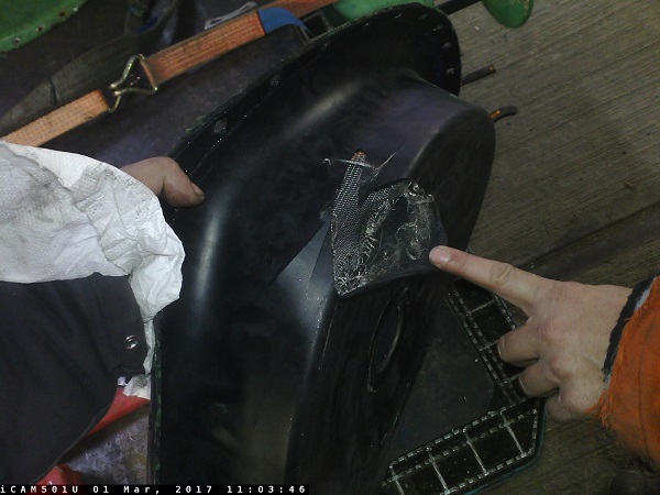
Never increase the air pressure more than that foreseen by stamp in actuator (maximum working pressure) the photo below shows what happens to an actuator where the valve was stuck and it was decided to increase the air pressure to try to unlock it.
www.bennypass.it
|