|
Difference between 4-20ma and fieldbus comunication
Main Differences with 4..20 mA technology:
Energy available
Connection topologies
Functionality
Configuration
Energy available
- The 4-20 mA analog signal is a "communication" system standard for industrial instrumentation
- The 4-20 mA current loop represents the transmitter measurement signal
- The current loop itself also powers the transmitter,
- The measurement signal is valid between 3.8 and 20.5 mA while, in the event of an anomaly, the signal goes to the selected alarm threshold of 3.6 mA or more than 22.0 mA
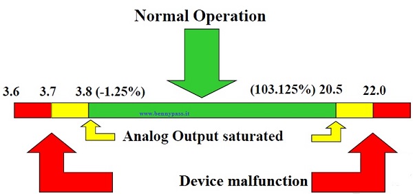 The most critical condition is when the instrument goes into alarm at 3.6 mA because the instrument must continue to operate with less than this current. The most critical condition is when the instrument goes into alarm at 3.6 mA because the instrument must continue to operate with less than this current.- This reduced availability of energy does not allow 4 ... 20 mA instruments to perform complex calculations and functionalities that would be feasible if there was more energy available.
note:
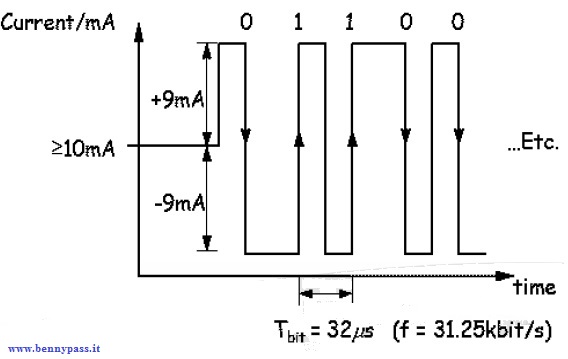
The fieldbus transmitter doesn't have this limitation, they have available more then 10ma
Communication and modulation with a current di 9ma like the photo below:
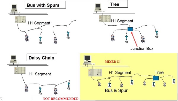
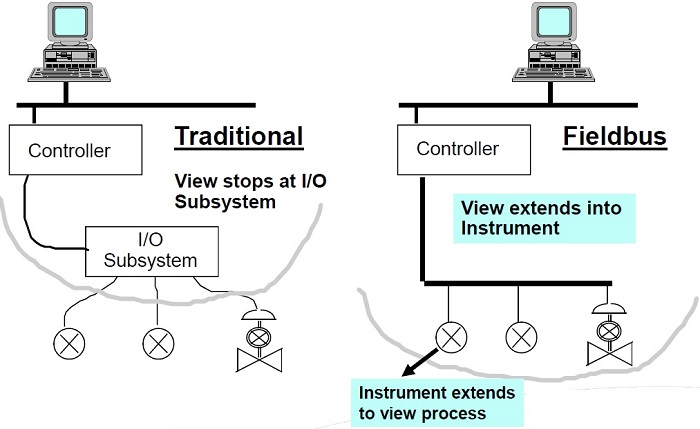
Connection topologies
|
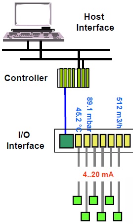
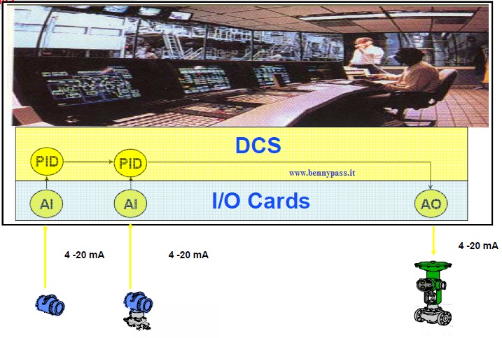
Each analog instrument is connected by two wires to
one I/O card that converts the 4..20 mA signal into a measurement in engineering format
|
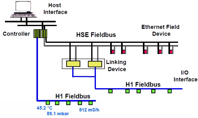
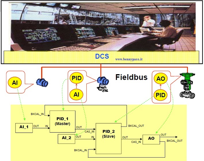
The FF instruments are also connected with two wires, but on the same cable pair can be connected more tools:
- The outputs of the instruments are already in an engineering format I/O cards disappear because of their function
- Analog Input (AI) and it is migrates within the instrument itself
|
See photo below :
Distinctive features of FF
Function Blocks
- Distributed control in the field LAS function (Link Active Scheduler)
- The types of communications used by FF
- Macrocycle and Determinism The DD and CFF files
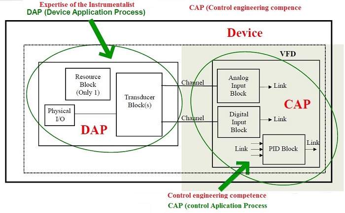
"Blocks" structure given in FF instruments
FF instruments contain many variables and information distributed / mapped in different "Blocks"
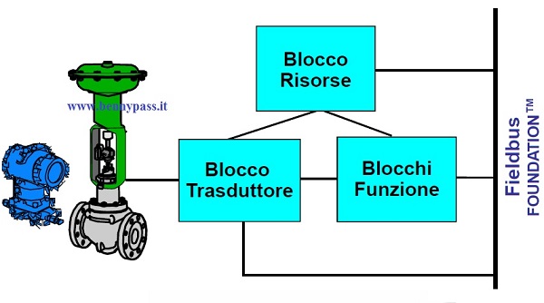
The FF instruments have at least 3 "Blocks"
Resource Block
Contains data describing the general characteristics of the device:
- Revisions
- Serial number
Transducer Block
Connection between the physical system (process) and the computer world (conversions)
- Acquisition and conversion of the process measurement in engineering format
- Limits and Calibration of the sensor
Function Blocks
Input (Analog Input) for transmitters or Output (Analog Output) for Actuators or control valve which are directly connected to the relative Transducer block from which they receive the measurements in engineering format, and apply the appropriate scales required for the specific process control.
Note: In addition there may be many other Function Blocks
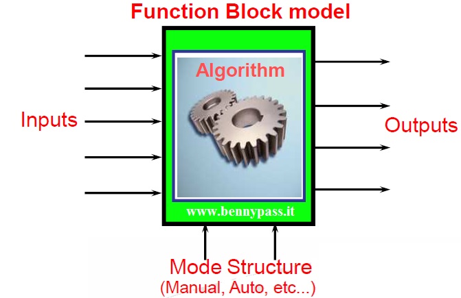
Function Blocks
What are they and what do they do?
The function Blocks are software "modules" that:
- receive input measures or variables ...
- they elaborate them through formulas / calculation algorithms
- produce the output results
See photo below:
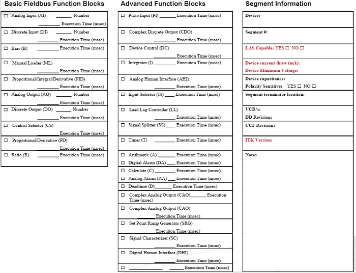
Function Blocks .... Which and how many they are?
|
Control and Calculate Class
- PID PID control
- EPID enhanced PID
- APID advanced PID
- ARTHarithmetic
- SPLT splitter
- CHAR signal characterizer
- INTG integrator/totalizer
- AALManalog alarm
- SPG setpoint ramp generator
- TIME timer and logic
- LLAG lead-lag
- OSDLoutput selector / dynamic limiter
- DENSdensity
- CT constant
- CT constant
- FFET flip-flop and edge trigger
- MBCS modbus control slave
- MBSS modbus supervision slave
- MBCM modbus control master
- MBSM modbus supervision master
|
Standard Function Blocks Class
- AI analog input
- DI discrete input
- MAI multiple analog input
- MDI multiple discrete input
- PUL pulse input
Output Class
- AO analog output
- DO discrete output
- MAO multiple analog output
- MDO multiple discrete output
- STEP step output PID
|
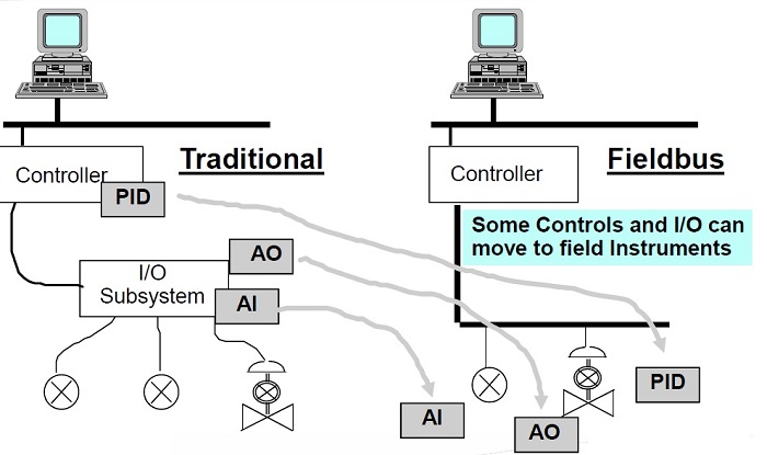
The function Blocks ... .. How to use them?
The Function Blocks can reside in the (traditional) Controller and / or in field instruments such as Transmitters or Positioners
- The control Function Blocks contained in an instrument can also be used by other instruments connected on the same segment / network
- By linking several Function Blocks to each other (link), a control strategy is designed
- If the Function Blocks are resident in the instruments, a distributed control in the field
Typical Applications
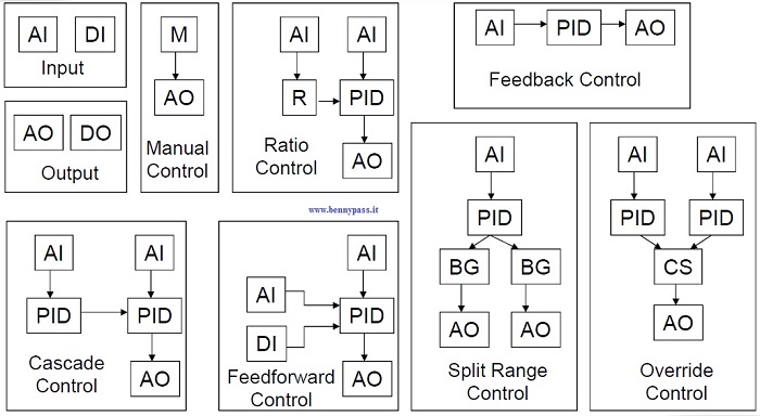
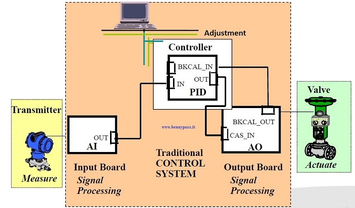
Function Blocks ... ..in traditional use
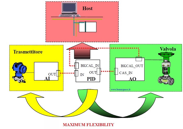
Function Blocks ... in the FF solution
Function Blocks….Controllo di CascataConvenzionale
Function Blocks .... Cascade Control with FF
Function Blocks..What does it change for the instruments?
- The FF tools are not evaluated only for their traditional measurement function but also for their own calculation capacity.
- If you want to achieve distributed control, you mustselect tools that contain number & typesFunction Blocks necessary for this purpose.
- It is also necessary to check their 'Execution Time'to understand if they are adequate to control performancerequests
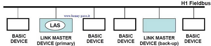
LAS (Link Active Scheduler) What is it?
The LAS function is the coordinator of an FF network
- Its function is also called "BUS Arbitrator" because one of its tasks is to manage the traffic of communications that must exist between instruments and between instruments and DCS
- It can be imagined as that of the "conductor" that coordinates the "orchestral" (field instruments) that they must follow a "score" (Macrocycle)
LAS (Link Active Scheduler) ... .. What is it for?
- Self-detection of instruments connected on the bus (live List)
- Automatic assignment of the network address and search with TAG
- Scheduled and Unscheduled communications management
- Time Distribution (Synchronization between instruments)
Note: The LAS function in limited mode can be developed also in field instruments (Backup LAS)
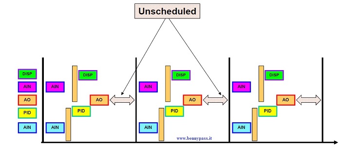
LAS (Link Active Scheduler) ... .. The types of Communications
Unscheduled (asynchronous)
- Client Server (one to one)
- Used for Configuration / Maintenance / Monitoring tool messages
- Transmitted only upon intervention / request by the operator
- Report Distribution (one to many)
- Used for Event / Alarm Notification and for Trend transmission.
- Transmitted from instrument with active alarms only when the LAS passes the Token
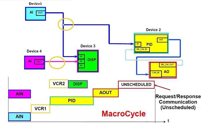
Scheduled (Sincrone)
- Publisher Subscriber (one to many)
- Used for the publication / exchange of variables between Function Blocks connected "link" to each other
- Exclusively dedicated to the realization of Process Control
The Macrocycle
Deterministic System
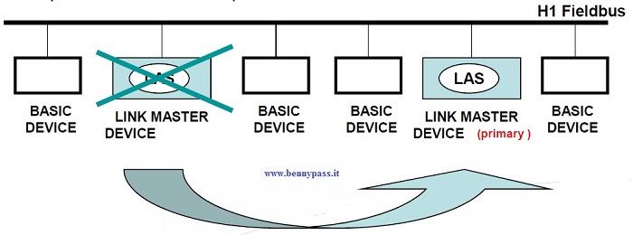
H1 - redundancy of the "LAS"
- FF distinguishes 2 types of instruments: "Link Master" and "Basic"
- Only "Link Master" tools support the Backup-LAS function
H1 - redundancy of the "LAS"
Multimaster system
- The FF distinguishes 2 types of instruments: "Link Master" and "Basic"
- Only "Link Master" tools support the Backup-LAS function
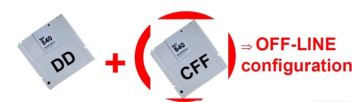
Device Description (DD)
The Device Description is an extended description of each object / parameter within the instrument, to be made available through the bus for readings / writes
The DD allows each Host FF to recognize and use, automatically, the corresponding Field Device
for example: It should be considered as the driver of a printer

Capability File (CFF)
The Capability File describes the resources of the tool type:
- Number and types of Function Blocks
- Function Blocks execution time (Execution Time)
- Default setting of the parameters / objects of the Function blocks ....
Advantages of Fieldbus
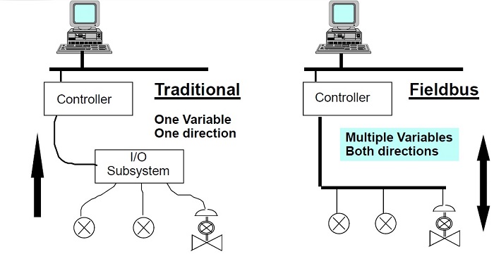
Analog / Digital communication
What are the differences between a communicationanalogue and digital in process automation?
- Transmission of only one process variable (the current value 4..20 mA)
- Recognition of connection problems (line interruption)
- Acknowledgment of instrument problems (Sensor Fail) in the form of output signal level 3.6 mA / 22.0 mA
|
- More than one variable can be transmittedprocess
- Each process variable is transmitted with theits Quality Status (Bad, Uncertain, Good)
- Process variables are transmitted in engineering and High resolution Format
- Diagnostic information about breakdowns in the instrument can be transmitted for Asset Management functions
|
Summary of the comparison
- The 4 ... 20 mA output signal, including the D to A converter will disappear
- The function of the I / O Card that converts the 4 ... 20 mA signal in digital format into the transmitter itself ...... The measurement is transmitted in engineering format (ex: 27.5 ° C or 300.45 mbar)
- It is not essential to set a measurement or output range in when the fieldbus instrument measures and transmits in digital format everything that is within the physical limits of the sensor ... the setting of the output field are:
- If you want to read the measurement as a percentage of the measuring range
- If the measurement is derived, for example a flow measured with a dP
- As simple information for the user or the DCS but has no effect on the calculations
- Multidrop topology, a twisted pair for multiple instruments
- More energy for instruments if we compare with the 4-20 mA current loops.
- More information available for the Monitoring and Diagnostics – control
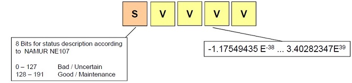
- Measurement available as a real value expressed in the selected unit of measurement and in addition a validation of the value itself (Status Byte)
- The measurements are composed of 5 Bytes (Input / Output)
- The 5 Bytes are composed of 4 Bytes floating point and 1 Byte of Quality Status
BAD + Detail
UNCERTAIN + Detail
GOOD + Detail
- Integration between Local Devices / Control System
- Better accuracy due to the absence of A / D and D / A conversions
- Less update / propagation delay of information due to fewer elements between the instrument and the DCS
- More Flexibility
Summary of advantages Reduction of:
- Connection cables and cabinets
- S. Barriers
- Input / Output Converters
- Power Supplies and protection
- Space for control rooms of the plant
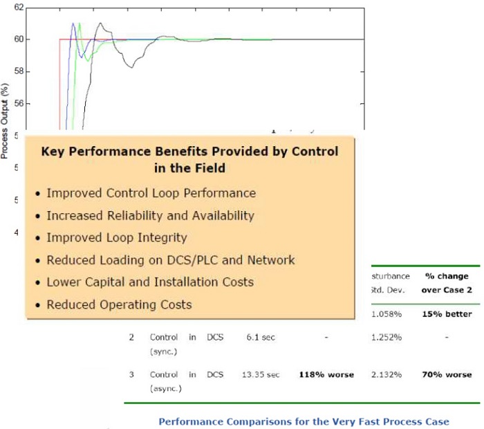
Comparative control tests in the field and traditional
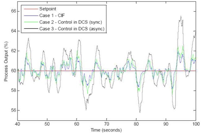
Control in the Field Provides Superior Reaction to Deterministic Disturbance in the Process
www.bennypas.it
|


