|
The base of Foundation Fieldbus
Introduction to technology
Definition of the field bus foundation
what is the fielt bus?
- Integrates sensors and actuators into the control system end automation
- Provides more information to the system than with traditional system
- It helps to create true distributed control
The technology base of FF
- The technology
- The BUS H1
- The bus H2 (HSE)
- Interoperability
- Certification of Products (issued by body Third)
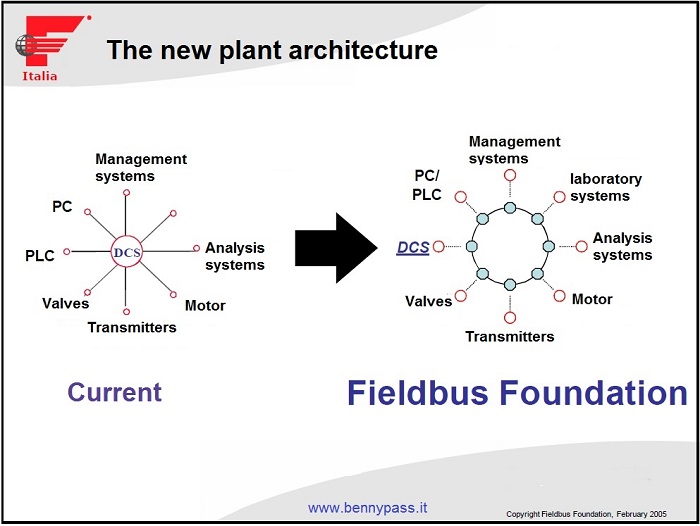
System information networks
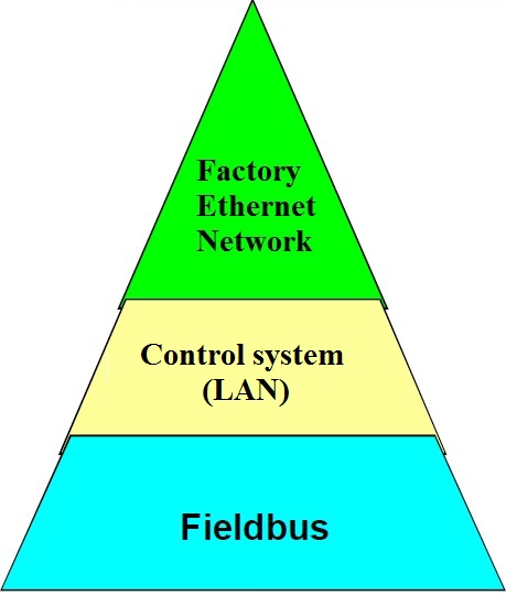 |
Office automation e rete computer
Control and monitoring system
Network for field instruments
|
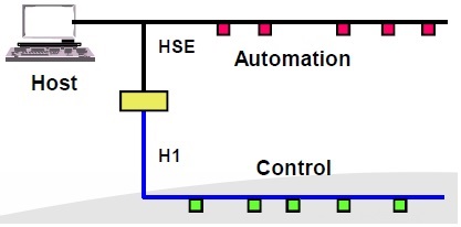
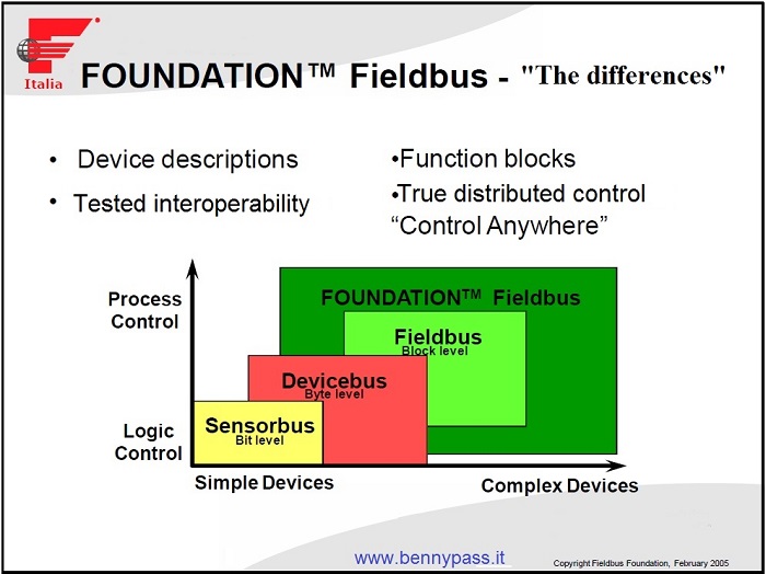
FOUNDATIONTM Fieldbus - what is it?
- An open digital communication protocol bidirectional which consists:
- a fast (backbone) network to meet the needs of factory automation
- a low-speed bus to meet the needs of process control
- Integration path to plant automation
- sensors and actuators integrated into the factory control system
- Significant cost reduction
- on the construction of the plant
- on the conduction operation
- on maintenance
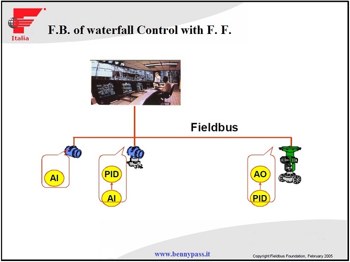
See photo below:
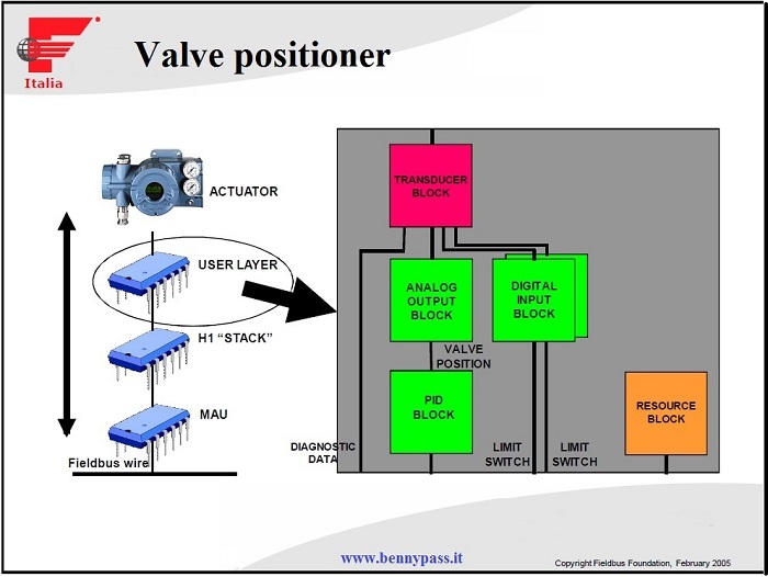
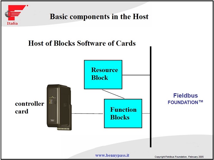
H1 User Layer - that is who makes the difference
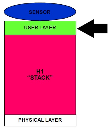 |
- It provides for the interface with the process
- Determines the interaction between the user and the system host
- Definition of the communication data and the function distributed in the field devices, in a common way for various instrumentation suppliers.
- deterministic scheduling of function blocks
- The host system interacts with the device without requiring a custom programming.
- Allows segment configuration in off-line mode (with tools disconnected or without segment availability)
|

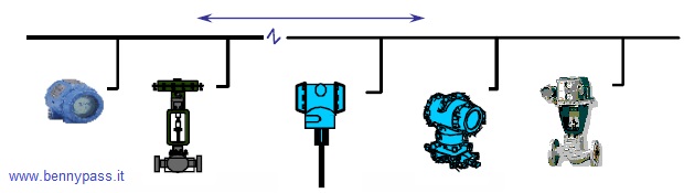
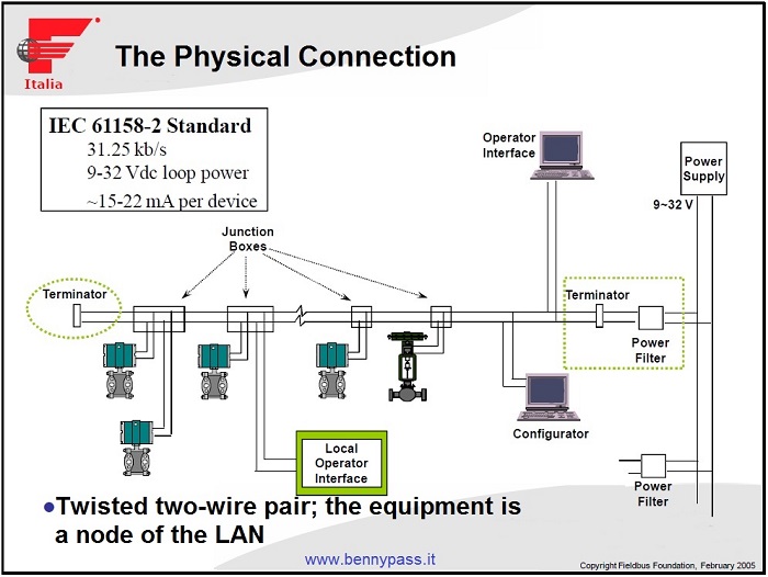
Definition of Bus H1
It is a digital LAN for bi-directional communication, multi-drop, and is connects field instrumentation, which exploiting the one's intelligence, realizes the true Distributed Control.
It is specifically designed to meet the needs of the Process Industry
below the example of two-way communication:
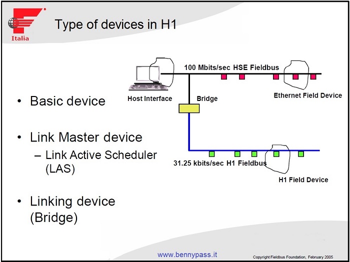
FF's Distinctive and Basic Elements
- Function Block
- LAS (Link Active Scheduler)
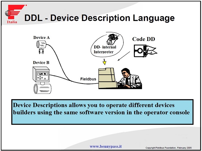
- DDL (Device Description Language)
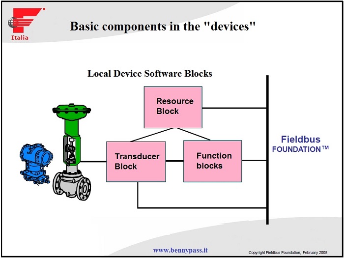
At least 3 FBs live on a device
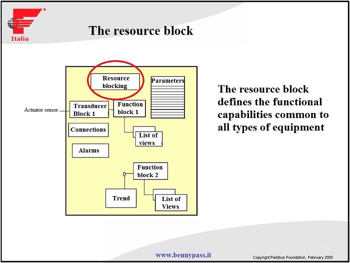
- Describes the characteristics of the device
- Contains the manufacturer's information
- Identify available resources and configurations
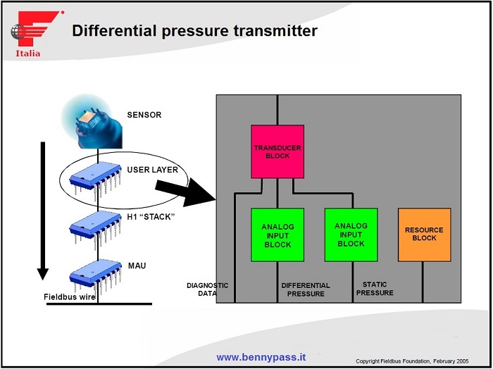
- Physical I/O interface with sensor or actuator
- Develop calculations for A / D conversion, linearization, etc.
- Transmit and / or receive data from / to Function Blocks
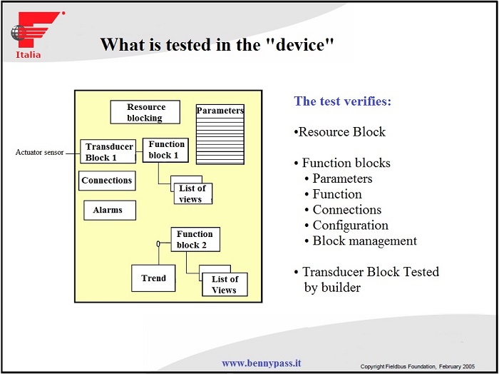
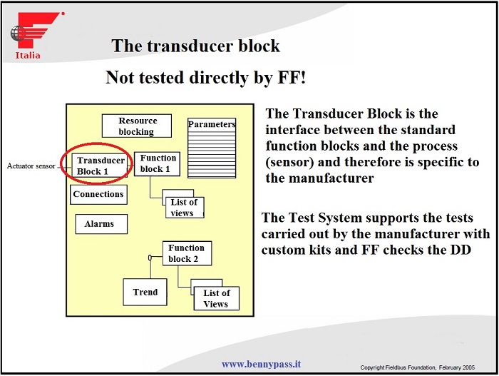
- The transducer block is the real window on the process and integrates diagnostic functions.
- Allows configuration and provides diagnostic information of the sensor and / or actuator
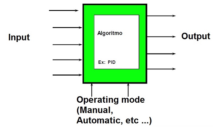
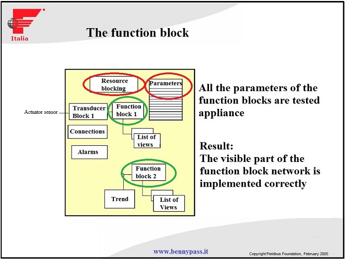
- They are the elements with the mechanisms and ability to communicate, calculate and interact with other devices
- At least one function block must be present in each device
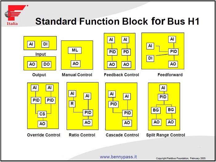
Standard Function Blocks
|
Basic Function Blocks
- Analog input
- Analog output
- Media & Earnings
- Control selector
- Discreet entrance
- Discreet output
- Manual control
- PD control
- PID control
- Report Control
|
Advanced function blocks
- Analog alarm
- Arithmetic functions
- Dead band
- Equipment check
- Input selector
- supplements
- Lead / Lag
- Ramp generator for
- setpoint
- Signal characterizer
- Splitter
- Timer
|
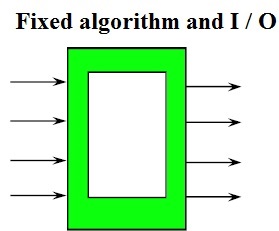
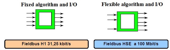
Fixed Function Block
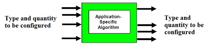
Flexible Function Block
FFB Extend the use of Function Blocks
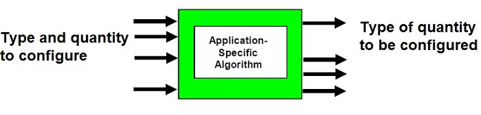
FFB provides a "container" for FFB-specific Application Algorithms that can be activated by means of configuration programs (eg. IEC 61131)
Examples of Applications with FFB
Sequence of Events
Motors Coordination
Data Acquisition Supervisor
Interface I / O subsystems
Batch Sequences
Burner Management
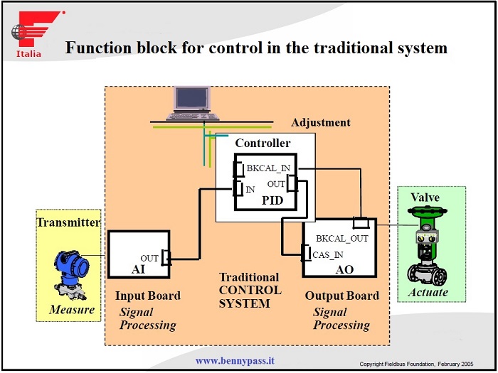
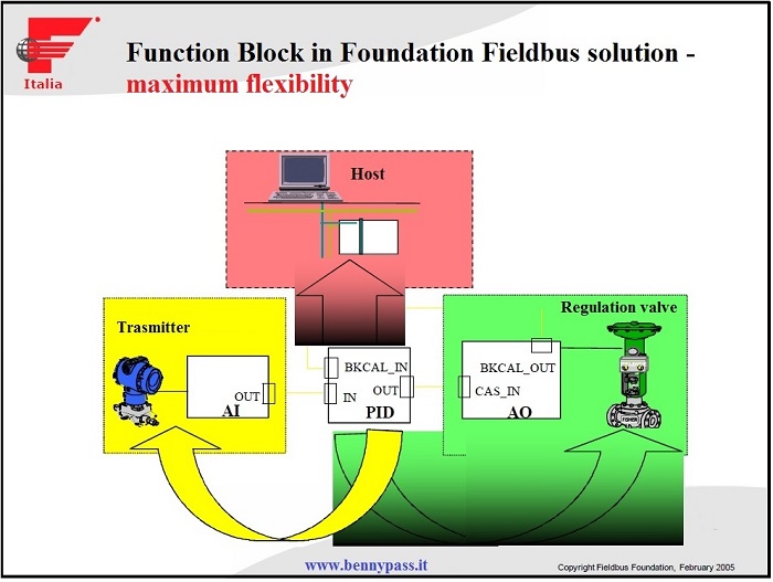
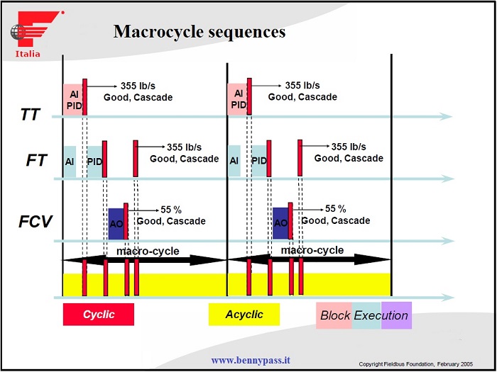
Use of Function Blocks
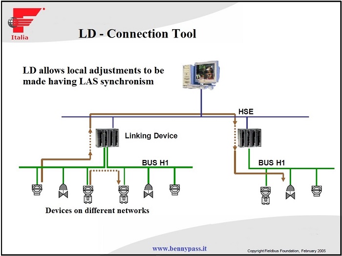
The adjustment on Local Devices it is possible by the Blocks Function and by the determinism of the transmitted signals. There are two types of communication in the Bus:
- Cyclic (Publisher / Subscriber) Adjustment signals
- Acyclic (Client / Server) Diagnostic Signals / Configuration
Specific function blocks allow diagnostics of Process, interacting the signals coming from different Device. Typical examples:
- Clogged impulse lines
- Leakage monitoring in the SPM (Statistical Process Monitoring) line
FF's Distinctive and Basic Elements
- Function Block
- LAS (Link Active Scheduler)
- DDL (Device Description Language)
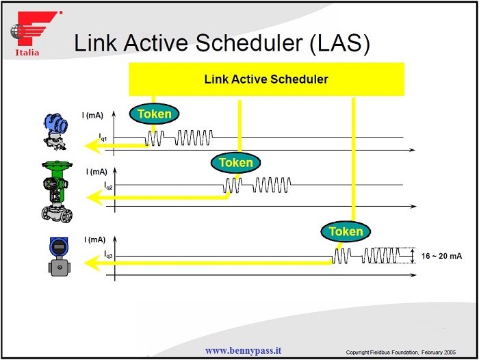
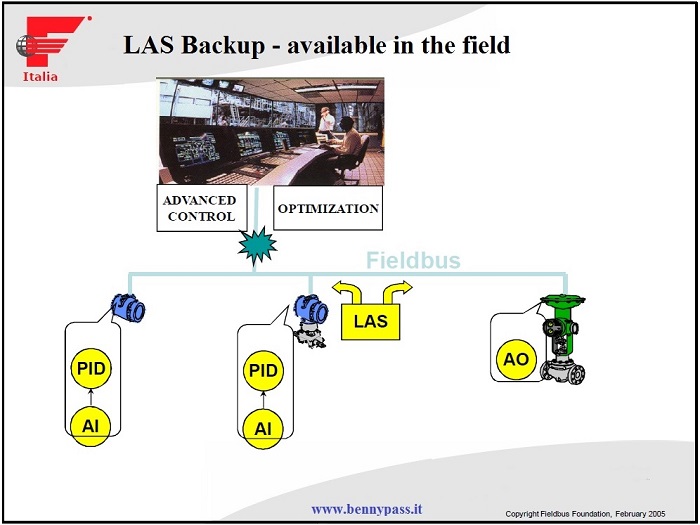
LAS arbiter of the Bus
- Auto-detection of the connection
- Automatic addressing and search by Tag
- Management of synchronous and asynchronous signals
- Bus time alignment clock
- Management of the back-up of the LAS in the devices
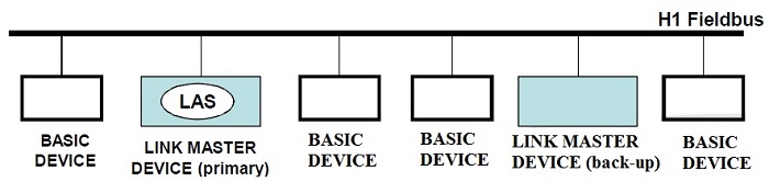
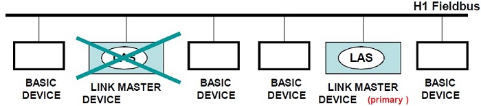
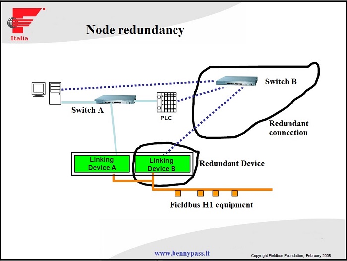
H1 - redundancy of the "LAS"
The LAS function is transferred to the back-up device when the primary LAS dies.
FF's Distinctive and Basic Elements
- Function Block
- LAS (Link Active Scheduler)
- DDL (Device Description Language)
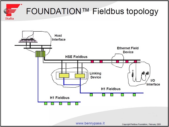
Foundation Fieldbus BUS (H2) HSE
Redundancy and logic control
HSE - High Speed Ethernet
The HSE Uses the same technology as H1 a User Layer level
- Function Block FB
- Device description (DDL)
HSE Uses technology Ethernet / Internet for communication
- Standard IEEE Physical Layer
- Internet Protocols Standard for "Stack"sasd
- Commercial Off The Shelf (COTS) Network Equipment
General Bus Features
- High speed at 100Mbits / s
- Foundation Fieldbus protocol
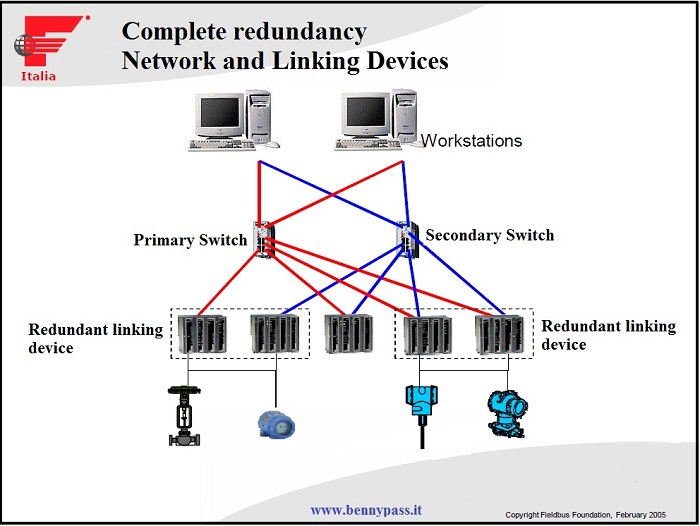
- Complete redundancy
- Open to other protocols and / or fieldbus
- Fixed / flexible function blocks (D / A)
- Cable connections (twisted pair) and / or optical fibers
- High performance STD equipment butwith low cost
General characteristics
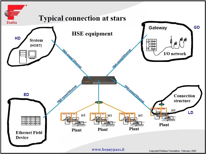
Solution based on existing standards IP e TCP/UDP Interfaced by standard equipment
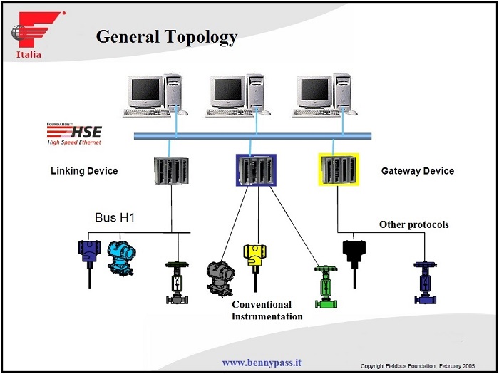
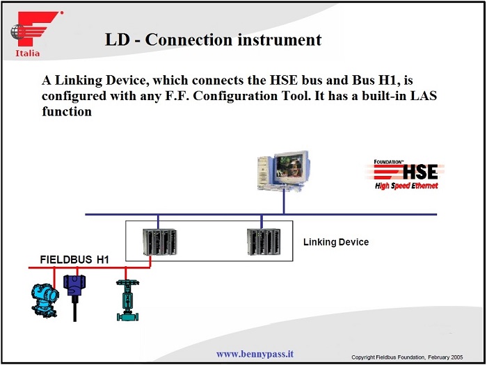
Linking Device (LD) Bus H1 F.F.
Ethernet Device (ED) Standard TCP devices
Gateway Device (GD) Other Bus Interface
Host Device (HD) System Interface

Flexible Function Block
FFB Extend the use of Function Blocks
FFB provides a "container" for FFB-specific Application Algorithms that can be activated by means of configuration programs (for example IEC 61131).
Examples of Applications with FFB
Sequence of Events
CoordinamentoMotori
Data Acquisition Supervisor
Interface I / O subsystems
Batch Sequences Burner Management
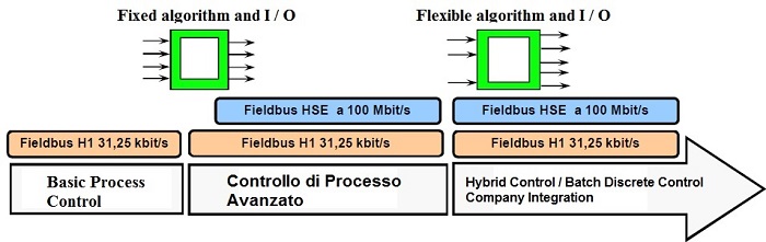
Process Control
|
|
 |
 |
Basic Function Blocks
- Analog input
- Analog input
- Analog output
- Media & Earnings
- Control selector
- Discreet entrance
- Discreet output
- Manual loader
- PD control
- PID control
- Report Control
|
Process Control, Advanced & Discreet
|
Basic Function Blocks
- Analog input
- Analog output
- Media & Earnings
- Control selector
- Discreet entrance
- Discreet output
- Manual loader
- PD control
- PID control
- Report Control
|
Advanced Function Blocks
- Analog alarm
- Arithmetic
- Dead time
- Equipment check
- Input selector
- supplements
- Lead / Lag
- Ramp generator for set point
- Signal characterizer
- Splitter
- Timer
|
Process Control, Discrete & Batch
|
Functional Blocks
- Analog input
- Analog output
- Media & Earnings
- Control selector
- Discreet entrance
- Discreet output
- Manual loader
- PD control
- PID control
- Report Control
|
Advanced Function Blocks
- Analog alarm
- Arithmetic
- Dead time
- Equipment check
- Input selector
- supplements
- Lead / Lag
- Ramp generator for setpoint
- Signal characterizer
- Splitter
- Time
|
Flexible Function Blocks
- Multiple Inputs / Outputs
- I. analogue 8 channels (MAI)
- U. analogue 8 channels (MAO)
- discrete 8 channels (MDI)
- U. discrete 8 channels (MDO)
- Application specifications (IEC 61131)
- Events Sequence
- Supervision data acquisition
- Batch sequencing
- Burner management
- I / O system interface
|
Foundation Fieldbus Interoperability Function guarantee
Definition of interoperability
These are the tests defined at the end of the year 2000, both for "Devices" and for control systems. They guarantee the complete functionality of the system.
Fieldbus FOUNDATION updates the list of supported host features and certified equipment on web site www.fieldbus.org
Ability to build a multi-field fieldbus system without losing functionality
- It does not mean interchangeability of the Equipment
- The approach must be systematic to allow automatic configuration
- The initial cost can be minimizedselecting the most suitable equipment
- Conduction costs can be reduced thanks to the availability of information provided by intelligent equipment
- The tests defined are:
- ITK4 for instruments with certificate issuance
- HIST for systems without certificate issuance
Foundation Fieldbus Certification
The guarantee of the standard
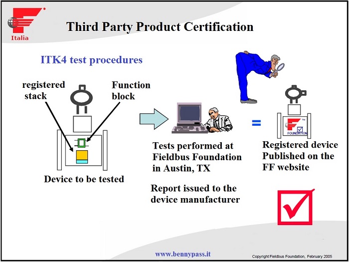
Certificate of Test Host Third Body
HIST (Host Interoperability Support Test) test procedures
Provide guarantees that a Host system is INTEROPERABLE with registered Fieldbus Foundation devices. It is a series of functional tests supported by the Host system, without constraints and each manufacturer defines which functions are supported.
For example:
- Initial Connection and Address Assignment
- Reading and Writing of Field Device Information
- Test of configuration of link objects and schedule
- Testing of the Device Description Support
- Testing of Mode and Status ; Testing of Alarms and Events
- Testing of View and Trend Objects ; Testing of Block Specific Behavior
What it means for the user?
- Ensures that the equipment of buildersseveral have been subjected to common tests
- The equipment is tested and verified bya Third Part
- Ensures that the certified equipment of different manufacturers have been tested with different host systems
- Confirm the common characteristics of theequipment
- Confirm the features supported by the systemshost
ITK4 - device tests
- Test of the configuration of the instrument and of the Function blocks
- Device Description Test (DD)
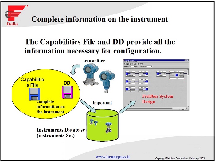
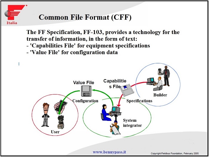
- Capability File Test (CFF)
- Physical Level Test Specifications
Content of the System Interoperability Test Host
Functional tests supported by the HIST test program:
- Initial connection and Address assignment
- Read and write information of the equipment Field
- Testing the configuration of connected objects and programming
- Test of the mode and status functions
- Test of the Alarms and Events functions
- Test of the View and Trend functions
- Test of the Specific Behavior of the Block
- Device Description Support Test
- Capabilities File Support Test (required for offline configuration)
Linking related files
Conclusion:
Although the fieldbus is an excellent system, the Oil&Gas industries still they have a lot hesitation about it , in fact, the fieldbus is not implemented to vital parts of plant such F&G system, or emergency systems, still they use the hardware philosophy
www.bennypass.it
|


