
Fieldbus Foundation H1
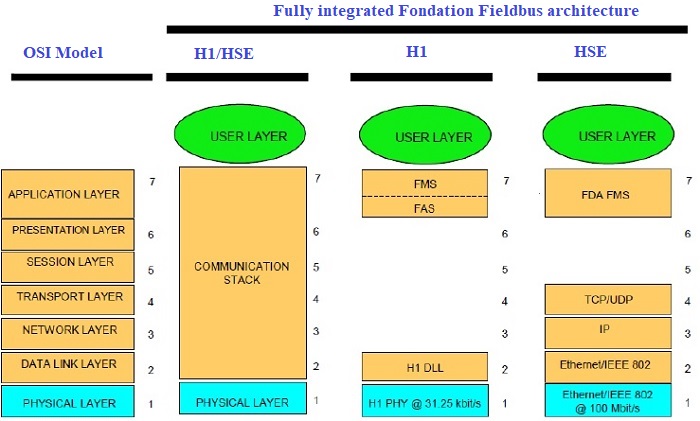
ISO/OSI Layer Model for Foundation
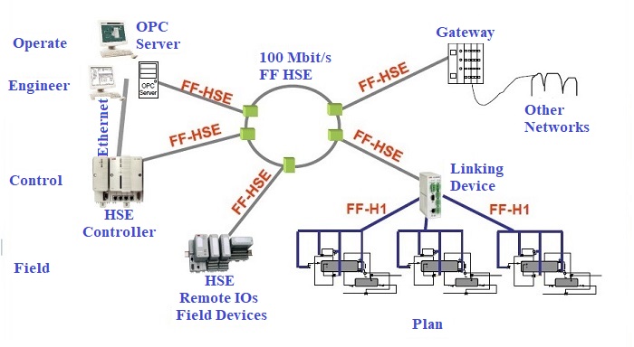
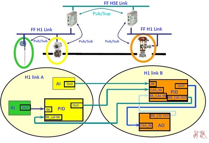
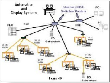
HSE - High Speed Ethernet Topology
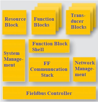
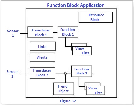
User Application Blocks There are three categories of function blocks:
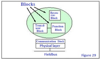
Resources Block: describes the characteristics of device, such as the name and serial number. Transducer Blocks: are used to manage the input / output functions required, for reading the sensors, and implementing commands.
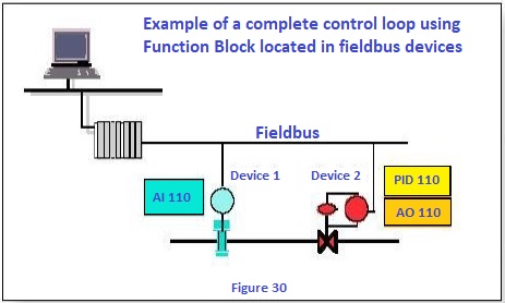
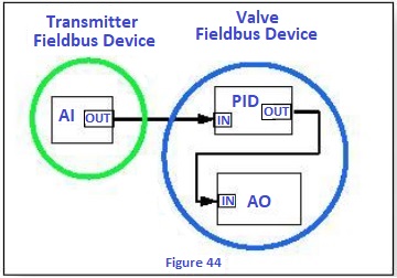
Example of loops
FF HSE Applications
Function Block: provides to implement the control system. The execution of each Function Block and very carefully scheduled. There may be multiple function blocks in a single User Application F.F. defines a standard set of ten Functions Block:
Fieldbus Device Definition
Fieldbus Device Definition
System Management Function blocks must be executed in precise and defined intervals in according to a correct sequence. The System Management synchronizes the execution of the Function Blocks and the communication of their parameters via bus; moreover, he takes care of other tasks, among which the automatic assignment of addresses to devices. All configuration information required for System Management is available via the VFD objects of each device
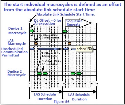
Function Block Scheduling
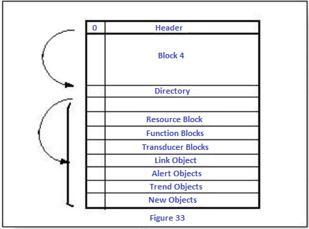
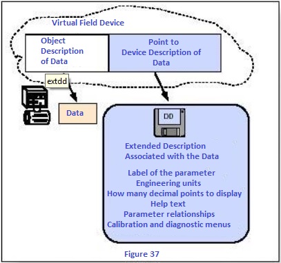
Device Description
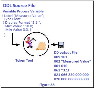
DD can be thought of as like drivers that we are used for computer peripherals; means that contains a whole series of information that characterize the device precisely, and transform the virtual description contained in the VFD into a precise representation of the physical object. The DD is written in a standard language, known as Device Description Language (DLL): a special program ("tokenizer") that translates the DLL's instructions into numbered strings, as you can see in the figure. A new device can be added simply by connecting it to the bus and providing the control system with the DD (supplied by the device manufacturer) of new device.
System Configuration The configuration of a fieldbus consists of two phases: System design, which is simplified by the possibility of both using the traditional 4-20 mA connections, and connecting multiple devices to a single wire and finally entrusting control and I / O management functions to the devices, with reducing the number of controllers and interfaces.
Configuration of the Devices takes place as shown in the figure by connecting the Function Blocks, an operation performed by software, that using the "virtual" description of the objects, rather than with "physical" connections.
After carrying out this and other preliminary operations, the computer that manages the configuration sending the necessary information for each device connected to the fieldbus, and if present, delegates the control of the fieldbus to the Link Master.
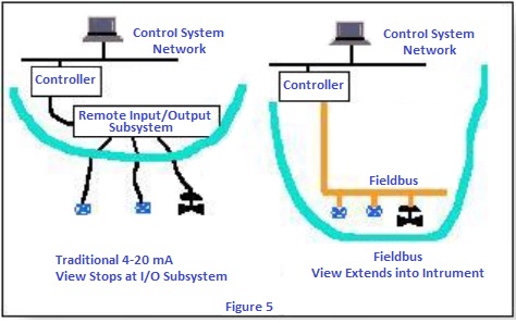
Connections with others bus A Linking Device is used to connect to a fast Ethernet (HSE) network. An I/O SubSystem Device is used to interface with other buses, such as DeviceNet and Profibus.
Benefits of the Foundation Fieldbus Reduction of wiring, control and I / O devices, lower costs due to ease of configuration and management of the system, easier maintenance due to the lower number of variables and parameters that to be controlled, and to the greater number of information coming from the field bus and manageable at a high level.
Comparison between different fieldbus standards
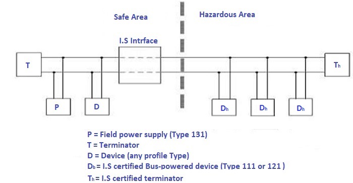
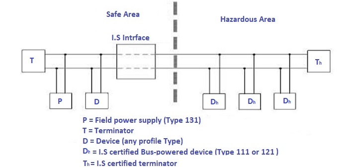
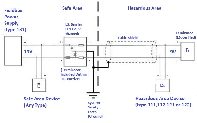
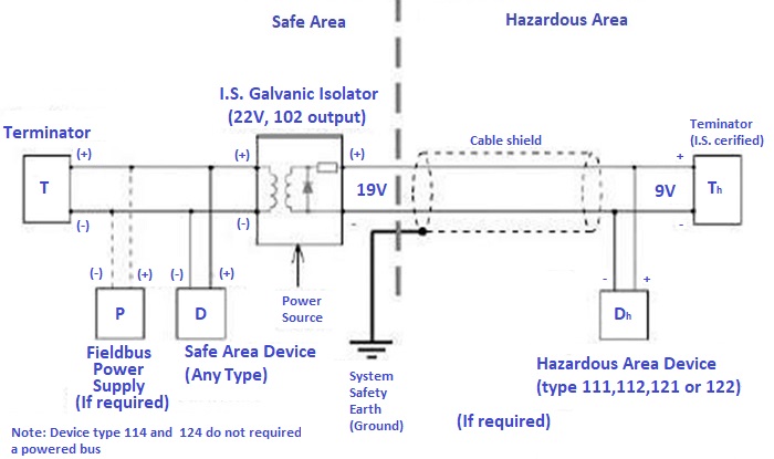
31.25 kbit/s Intrinsically Safe System Intrisic Safety is a method that ensures the safety of electrical components where flammable materials are present. Within the environment that is being considered, there are hazardous areas and safe areas. Hazardous areas are those which flammable elements are present in the air (oil and its derivatives, coal, alcohol, flour, etc.). The I.S. method it is proposed as an alternative to the traditional ones and guarantee the security in these areas. The system, consisting of an I.S. terminal for the risk area and an I.S. Interface for the safe area, it is not able to cause any risk of explosions in the air. The electrical energy present in the hazardous area is limited to such a level, that any spark or hot surface is too weak to cause an explosion. On the market there are many different components. the recomandation from the FF is that components must be compatible with a common connection bus. These specifications, derived from the IEC 1158-2 standard, and define eight types of devices for communication on the fieldbus, which is four are suitable for connection to an I.S fieldbus. in a risky area. they are the: 111, 112, 121, 122 (with types 111 and 121 that are powered only by the bus, unlike the other two that have one or more power sources in addition to the one supplied by the bus). These devices are characterized by the fact that they do not introduce any electric energy on the field bus, both during reception and transmission of the signals. This happens thanks to the MAU (Medium Attachment Unit), which is a unit contained in the devices and which takes care of the transfer of signals (in reception and transmission),the bus is equipped with its own power supply. In the figure below we can see a schematization of the system, as we are describing it. On the left side is the safe area, while on the right side the dangerous area, with the respective devices and two terminals on the ends, which are two simple resistances.
There is a P power source and an I.S. interface. Note that, while the hazardous area they can be only between four types shown above, there are no type constraints in the safe area.
There are two ways to prevent higher than expected values in the system, or through an I.S. barrier. or through a galvanic isolator. Both are mounted in the safe area, unless the certification allows installation in the hazardous area, even with the addition of protection techniques. A typical I.S barrier, it consists a network where they are connected in parallel the zener diodes, resistors and protection fuses. Its function is to divert overvoltage or overcurrent to earth, before they can cause an explosion in the hazardous area.
The output voltage from the power source must be coupled with the voltage which the I.S. it is able to operate, after that the zener diodes intervene to send the excess voltage to earth. The galvanic isolator, it is made up of transformers or optical couplers, which allow a physical separation of the circuits, with a ensuring and more effective isolation
www.bennypass.it |
||||||||||||||||||||||||||||||||||||||||||||||||||||||||||||||||||||||||||||||||||||||||||||||||||||||||||||||||||||||

+(39) 347 051 5328
Italy - Kazakhstan


09.00am to 18.00pm
About
We offer the best and economical solutions, backed by 27+ years of experience and international standards knowledge, echnological changes, and industrial systems.
Our Services
Marketing Materials


Marketing Materials1


