
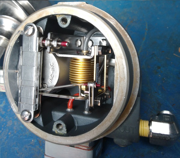
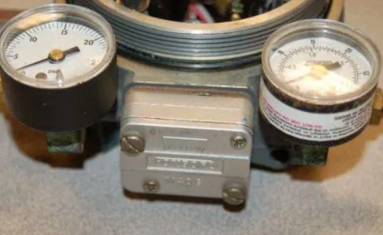
Working principle of Current/Pressure managed by a I/P converter indroduction In the Current to Pressure converter (I/P), usually the current signal as 4 – 20 mA, also the continuous supply of 20 P.S.I to the Flapper Nozzle assembly is required. As soon as the current signal will activate simultaneously the Electromagnet gets activated. Let's to start with pneumatic control only The photo below showing a regulator 3 - 15 psi without controlling 4 - 20 mA, of course old technology but the functionality is exactly the same
The continuous action pneumatic controller is an instrument capable to maintain a variable quantity (for example a flow rate, a temperature, a level, or control a damper.) at a predetermined value. Therefore, the controller forms the basic element of a pneumatic continuous control loop. The preset value or set point can be varied according what you need, if positioning an index (index of the set-point), on a scale whose graduations are the same as the set quantity. The term continuous controller arises from the fact that the instrument continuously compares the value assumed by the controlled quantity with the predetermined value which represents the set point. In the event of difference between the two values, i.e. a deviation, the controller intervenes to cancel it, suitably graduating the valve opening.
This type of controller receives an inlet pressure (Pe) which is proportional to the controlled variable and outputs a modulated pressure (Pu) which represents the control regulating. The inlet pressure (Pe) comes from a pneumatic transmitter and therefore ranges from 3 to 15 psi. The outlet pressure (Pu) is sent to a pneumatic servomotor that controlling a valve with variation of 3 to 15 psi. The value of outlet pressure (Pu), or control variable, depends on the magnitude and sign of the deviation and on the actions of the controller. Continuous action pneumatic control can be:
Note: The proportional action is a basic action, the other two are add-on actions. Continuous pneumatic controllers are divided into:
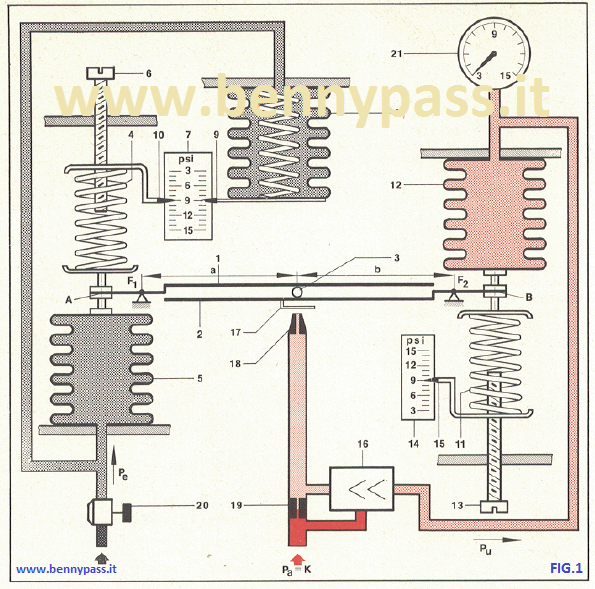
Working principle of proportional action Consider the principle diagram shown in the figure 1 above. The forces involved are applied to two levers (1 and 2), which are respectively fulcrate in F1 and F2. The connection between two levers is achieved by means of a pawl (3), which can be translated parallel to the arms of the two levers. At the end (A) of the lever (1) the following forces act in the opposite direction:
The spring (4) controlled by screw (6) has an index (set-point index) that moves in front of the scale (7) calibrated in psi. The Pe. is also sent to the indication bellows (8), whic is the sensitive element of indicating part controller. The elongations of (8), proportional to Pe, are transmitted to the index (9) which moves on the same scale (7) as the index of the set-point (10). At the end (B) of the lever (2) the following forces act in the opposite direction:
Pu represents the controlling value. The two bellows have the same section. The spring (11), controlled by screw (13), has an index (15) which moves in front of a scale (14) calibrated in psi. The two springs (4 and 11) can be loaded so as to simulate a variable pressure from 3 to 15 psi, ofcourse depending on the position of their index on the relative scales. The movement resulting from the out of balance of the forces acting on the two levers is transmitted to a simple modulator group (17-18-19). The modulated pressure is amplified by an amplifier relay (16) and then sent both to the controller output and to the bellows (12). A pressure reducer (20) and a pressure gauge (21) have been added to the diagram. The first allows to vary the Pe and second to measure the Pu.
Conclusion As you can see this instrument it is not inferior to the I / P converter, there is no electrical power here but only pneumatic controller. This type of instrument is still very useful especially where electrical power is not available like small platform, etc. Unfortunately, it is an outdated technology because this type of instrument actually turns out to be very expensive and very sensitive. I personally love the old technologies because it is possible to check and calibrate everything without electronic circuits. If damaged the eletronic circuit unfortunately everything has to be changed the entire instrument
I/P converter 4 - 20mA Below the photo with I/P converter from FOXBORO Manufacture
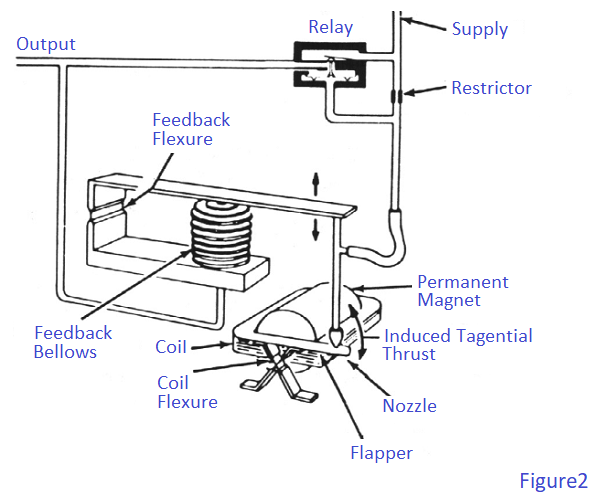
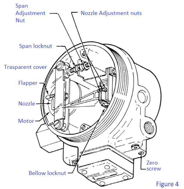
As you can see something change between pneumatic controller and electronic controller. The functionality remain exactly the same Principle of Operation A dc milliampere input signal is converted to a proportional pneumatic output signal in the following manner (see Figure 2). A coil positioned in the field of a permanent magnet reacts to the current by producing a tangential thrust proportional to the input signal flowing through it. The thrust, acting through coil flexures, varies the gap between a flapper and a nozzle. This causes a change in the output pressure of the relay, which is also the converter output pressure. This pressure is fed to a feedback bellows which exerts a force on a feedback flexure to move the nozzle and establish a throttling relationship between the flapper and the nozzle.
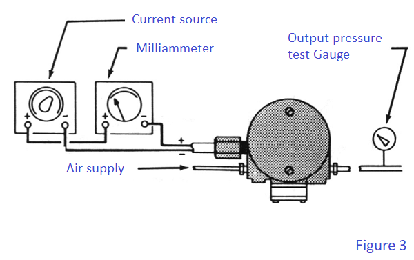
Adjustment and calibration For simplicity, the procedure below assumes a converter with a 4 to 20 mA input and a 20 to 100 kPa or 3 to 15 psi output. For other ranges, substitute the applicable values. The specific input and output are listed on the converter data plate. Calibration setup is shown in Figure 3 below:
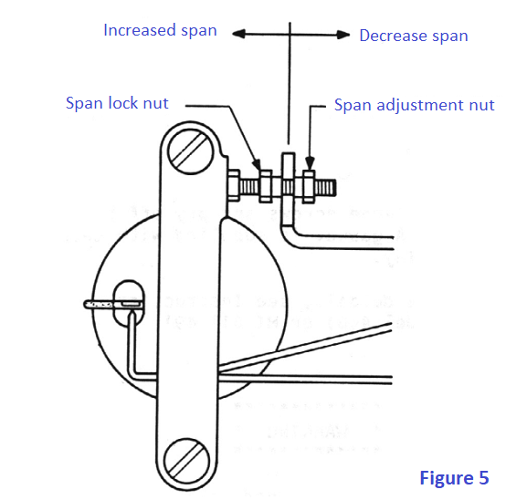
Note: Any adjustment to the span will interact with the zero adjustment and will change the initial zero setting. Therefore, any adjustment made to the span must be followed by readjustment of zero.
CAUTION: The span locknut must be loosened prior to span adjustment. Do not force nuts against each other to make small span changes. Forcing nuts together could result in stripping of threads.
CAUTION: Do not overtighten span locknut when locking in place as threads could become stripped.
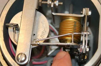
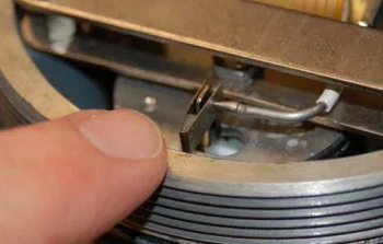
Conclusion As you can see, the calibration of I/P converter is far much simpler than the pneumatic controller. Praticaly when the electric current passes through the coil, it produces a magnetic field which reacts against a permanent magnet’s field to generate a torque. This torque causes the coil to rotate counterclockwise (as viewed in the photos 7 and 8 below), with the baffle connected to the rotating assembly. Thus, the baffle moves like the needle of an analog electric meter movement in response to current: the more current through the coil, the more the coil assembly moves (and the baffle moves with it). The nozzle faces this baffle, so when the baffle begins to move toward the nozzle, backpressure within the nozzle rises. This rising pressure is amplified by the relay, with the output pressure applied to a bellows. As the bellows expands, it draws the nozzle away from the advancing baffle, achieving balance by matching one motion (the baffle’s) with another motion (the nozzle’s). In other words, the nozzle “backs away” as the baffle “advances toward:” the motion of one is matched by the motion of the other, making this a motion-balance instrument.
The photo 8 shows the baffle and nozzle in detail Increased current through the wire coil causes the baffle to move toward the right (as pictured) toward the nozzle. The nozzle in response backs away (also to the right) to hold the baffle/nozzle gap constant. Interestingly the model E69 transducer employs the same pneumatic amplifying relay used in virtually every Foxboro pneumatic instrument (see photo 9)
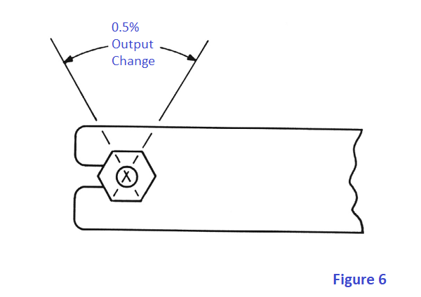
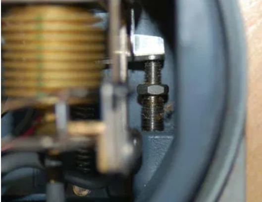
This amplifying relay makes the system more responsive than it would be otherwise, increasing sensitivity and precision. As in all instruments, the zero adjustment works by adding or subtracting a quantity, while the span adjustment works by multiplying or dividing a quantity. In the Foxboro model E69 transducer, the quantity in question is motion, since this is a motion-balance mechanism. The zero adjustment adds or subtracts motion by offsetting the position of the nozzle closer to or farther away from the baffle. A close-up photograph of the zero-adjustment screw shows it pressing against a tab to rotate the mounting baseplate upon which the coil unit is fixed. Rotating this baseplate add or subtracts angular displacement to/from the baffle’s motion:
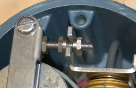
The span adjustment consists of changing the position of the nozzle relative to the baffle’s center of rotation, so that a given amount of rotation equates to a different amount of balancing motion required of the nozzle. This adjustment consists of a pair of nuts locking the base of the bellows unit at a fixed distance from the baffle’s center of rotation. Changing this distance alters the effective radius of the baffle as it swings around its center, therefore altering the gain (or span) of the motion balance system:
www.bennypass.it |

+(39) 347 051 5328
Italy - Kazakhstan


09.00am to 18.00pm
About
We offer the best and economical solutions, backed by 27+ years of experience and international standards knowledge, echnological changes, and industrial systems.
Our Services
Marketing Materials


Marketing Materials1


