
|
The pressure transmitter Introduction Pressure transmitters are versatile devices based on a simple working principle. Pressure is a primary value in instrumentation and control, and it can also be used to calculate other variables, such as level and flow. There is a wide variety of pressure transmitters in the market for applications with different needs. The way we measure pressure in our processes can vary depending on what type of pressure you are interested in. If you only want to know the pressure itself, then a pressure gauge will show you the absolute or gauge pressure. If you want to use pressure to measure a variable such as flow, you need a differential pressure (DP) transmitter. The first pressure transmitters in the instrumental field was very big, they read a value and convert direct the signal pressure in pneumatic signal for pilot the output. Let's see how work it Pneumatic pressure transmitter
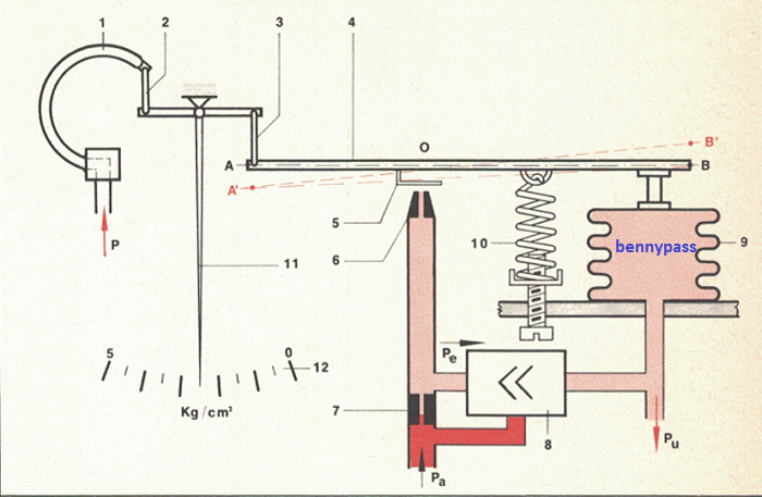
The pneumatic pressure transmitter is an element of the pneumatic regulation circuit that transduces a pressure, in this case a pressure in a modulated air pressure of 3 to 15 psi. The components:
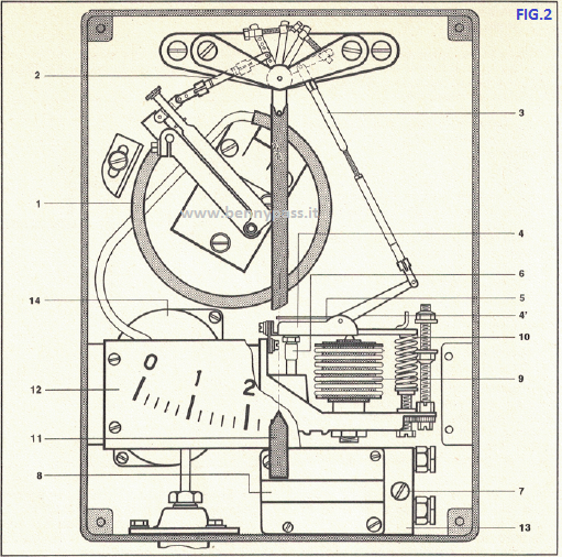
Description The transmitter in question is of the displacement equilibrium type. The pressure to be transmitted (P) is sent to sensitive element, in this case is a Bourdon spring (for low pressures it is a bellows), the displacements are transmitted to a measurement index and a simple modulator unit. The measurement index moves in front of a graduated scale in pressure units. The measuring range or transduction range of the transmitter the index is O - 5 Kg / cm 2. The pressure modulated by the modulator group (Pe) is amplified both in pressure and in volume by a pneumatic amplifier relay and sent to the transmitter output. The transduction system is reacted in such a way as to determine a proportionality between the pressure to be transmitted and the outlet (Pu). The transmitter is powered with a constant air pressure (Pa) of 20 Psi Working Principle The transmitter is schematically represented in the figure above Assume that the transmitter is in equilibrium and the pressure to transmit (P) increases. The free end of the Bourdon spring (1) rises and through the tie rods (2 and 3), brings the end A of the lever (4) to point A . The lever is pivoted at point B (mobile fulcrum). The lamina (5) thus approaches the nozzle (6), with the consequent increase in the modulated pressure (Pe) downstream of the restriction (7). The new pressure, suitably amplified by the relay (8), is sent both to the output (Pu) and reaction bellows. Inside the reaction bellows (9) the pressure (Pe) exerts a force (Fe) upwards, greater than that previously exerted, so the end B of the lever (4) moves to point B, while the other end of the lever remains fixed at point A, because it is bound by the pressure to be transmitted. The displacement (B-B ') is made proportional to the outlet pressure (Pu) by the spring (10). The new position of the lever tends to decrease the outlet pressure, because it moves the foil away from the nozzle. The transmitter returns to assume a condition of equilibrium when the P has assumed a value such as to cause a displacement BB at the end B of the lever (4), proportional to the displacement AA of the end A of the same lever, caused by pressure (P) that to be transmitted. In fact, considering the two similar triangles (AA'O and BB'O) we can say that: Side AA is proportional to side BB . Side AA is proportional to P. The P is proportional to side BB. The side BB 'is proportional to Pu. definitely: The P is proportional to the Pu Below the photo with all details of pneumatic pressure transmitter
Conclusion If we consider a decrease of pressure that will be transmitted, it is easy to verify that there is a proportional decrease in the outlet of pressure It can therefore be concluded that for each value assumed by P, within its range, there is a certain value of Pu This type of transmitter is really very old, but we are ensure it is still used, especially where the power supply is not available. This type of transmitter can read values with unique precision. The system working with balance of forces and not by transducer and microcontroller like electronic pressure trasmitter. Remember the transducer of electronic trasmitter (new technology) send a signal analogic to the internal microcontroller of trasmitter, the microcontroller trasform the signal 4 - 20 mA in digital, the microcontroller working in digital mode (0 and 1), so the signal is digital and then converted to analog (dirty analogic not clean), the people that working with microcontrollers know the sense. This is the reason why all trasmitters in the manual they write always error of +/- 0.5%. Is small error but with penumatic trasmitter in good condiction the error is pratically zero.
Electronic pressure transmitter (analogig only) The way we measure pressure in our processes can vary depending on what type of pressure you are interested in. If you only want to know the pressure itself, then a pressure gauge will show you the absolute or gauge pressure. If you want to use pressure to measure a variable such as flow, you need a differential pressure (DP) transmitter. We can find transmitters with many types of pressure sensors on the market – capacitive, piezoelectric, resonant silicon, and more. The most commonly used is the capacitive, so we're going to talk about this: The pressure applied to capacitive cells will produce a change in the capacitance of the sensor. This change will affect the oscillator frequency, and the pressure transmitter will detect this change. Then the transmitter translates this data into a standard output signal that we can read.
There are two types of pressure transmitter:
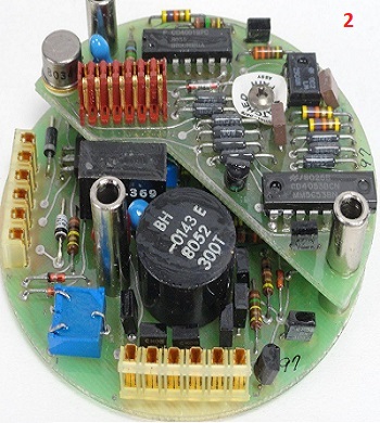
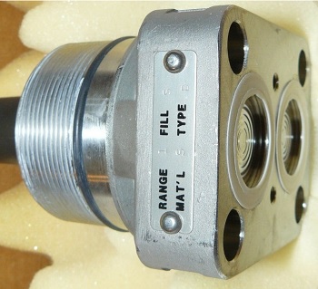
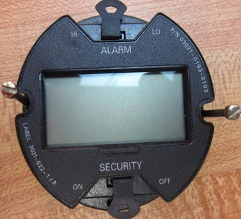
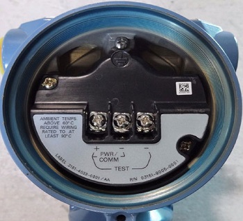
The analogic transmitters are first transmitters which replaced the 3 - 15 psi (pneumatic). The first transmitter was made by Rosemount 4 - 20 mA output. the components are described in photo below:
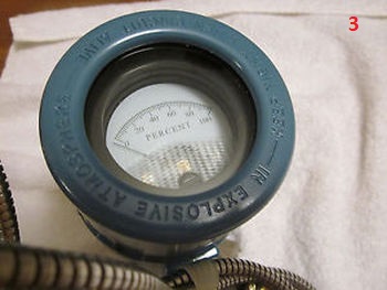
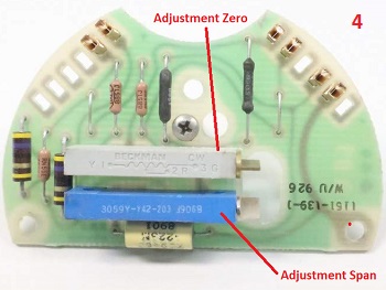
As you can see from the photos above this was a 4 - 20mA analog circuit, there was no microcontroller but only CMOS, in addition there was no digital display but a galvanometer (see photo 3). For calibration did not exist hart communicator but only adjustment trimmer for span and zero like in photo 4, of course for the calibration it was spend a lot time because to reach the correct range it had to be done via hydraulic pump the ramp several times and then always adjust the zero span until the exact range was found. Conclusion This was the history of pressure transmitters (Rosemount). From output transducer till out 4 - 20 mA was strictly ANALOGIC only. The difference between new technology and old technology like transmitter above is same between CDs audio with vinyl disk audio, the sound of vinyl disk is perfect because is analogic only and not digital like CD, anyway both disk working properly, but are not same.
Electronic pressure transmitter (Digital/Analogic) Introduction The new technology of pressure transmitters offers several options like in details below:
There are many other things, but the most important are those described and I want to underline them. As you can see with new technologies there is a lot of improvement Like all other transmitters, a pressure transmitter consists of electronics connected to a sensor. We can find transmitters with many types of pressure sensors on the market like in details below:
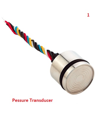
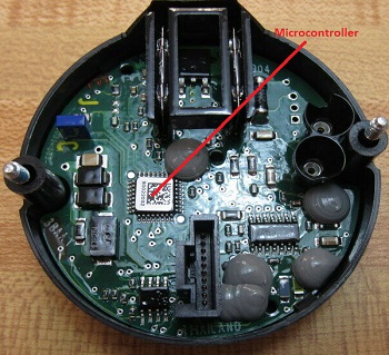
For understand how all transducers work see the article here Working Principle of pressure transmitter The most used transducers are Piezoresistive Transducer and capacitive Transducer, in this article we focus on Piezoresistive Transducer. Below the photos with all parts of new pressure Transmitter
As you can see from photos above the new models of transmitters is installed a microcontroller. This is reason why there is a lot function. The pressure transmitters are often very customizable by pressure range, accuracy, connection type, output, IP class, and even more variables. With so many applications, in order to chose the right pressure transmitter, we have to look into what types of pressure transmitter are there, what do pressure transmitters do and how do pressure transmitters work? The pressure transmitters measure pressure in various mediums (liquids, fluids, gases) and alert their users when a wide difference in range occurs. This is how pressure transmitters help prevent accidents in industrial processes. Although all pressure transmitters have pressure measurement function in common, the applications may differ a bit depending on different types of pressure transmitters. Below the Main Types of Pressure Transmitters
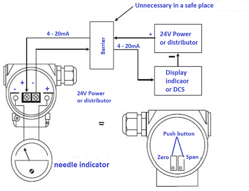
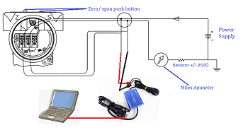
To put it simply, pressure transmitters convert the mechanical pressure into analog electrical signal. Pressure measurement is based on capturing the changes in voltage. The pressure on the pressure transmitter acts as a force on the diaphragm – depending on the applied pressure the diaphragm either expands or compresses, and the resistance value changes accordingly. The value is then transmitted as an electrical signal. When a certain change of pressure occurs, pressure transmitters can be used to notify that something changed in the process. Typical connection of pressure transmitter Typical connection between Transmitter and DCS with zener barrier
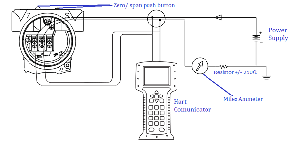
Typical connection between Transmitter and hart communicator (test mode)
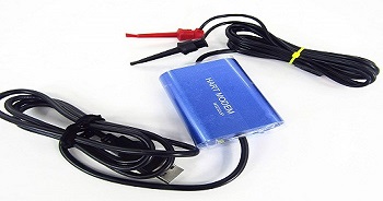
Almost all transmitters are equipped with hart protocol, in some cases there are also the software for communicate directly with the laptop. Important must be available the converter USB to hart protocol (see the photos below). Normally the software and the USB converter are supplied direct (if required) from manufacture
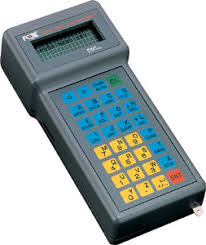
As you can see the hart protocol is one of the most beautiful things that can exist for instrumentation, but in some cases the hart protocol can generate problem. The hard protocol of transmitter reduce the execution of internal program a few milliseconds, is not so much, but for some parts of plant like Antisurge valves of compressor the milliseconds are very important for protection the centrifugal compressor. On request there are also transmitters without hart protocol, just for increase the speed of execution program. There are also software that communicate between transmitter and laptop direct with internal program, or some manufacture like Fuji or ABB they offer a specific communicator that working direct with internal program of transmitter (see photo below)
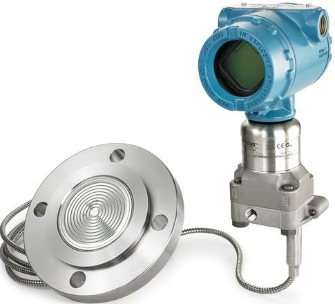
Pressure transmitter with Remote seal
A remote seal, also referred to as a chemical or diaphragm seal, is connected to the measuring instrument using a direct connection or capillary. The instrument side of the seal is separated from the process media by a flexible diaphragm. The chamber between the diaphragm and the instrument contains system fill fluid, which transfers the pressure of the process media. When fluctuations in pressure of the process media occur, the change is transmitted across the flexible diaphragm through the system fill fluid, which is hydraulically transmitted to the measuring instrument. This type of instrument is used a lot where the process may be sour gas, or corrosive substances, let's say it is a protection for the personnel that working on the instruments The differences between traditional transmitter and transmitter with remote seal are described below:
Note: If will be damaged the capillary or lost the internal fluid of transmitter, the transmitter should be replace, unless the material for repair and machine for making the vacuum inside the capillary are available. It is possible to do something on the transmitter mounted directly on the flanges, but it will not be easy to remove all the air inside especially when the range of transmitter are few millibars. A bubble that remains inside could be an error of 10 or 15 mbars
Conclusion There are also fieldbus and profibus transmitters but on these two points I send you to the article Fieldbus here 1 - 2 or Profibus here. In the last few years anything that does something is managed by a microcontroller. Digital electronics is everywhere also in the pressure transmitter. Sometimes you have to be very careful to buy something like a pressure transmitter. What matters is the reliability and not the functions that an instrument has. There are many instruments that are very nice, like display LCD, or easy calibrations, but then you discover that maybe one of them goes into fault without any reason. Stopping a plant for a transmitter is a significant error and economic
www.bennypass.it |


+(39) 347 051 5328
Italy - Kazakhstan


09.00am to 18.00pm
About
We offer the best and economical solutions, backed by 27+ years of experience and international standards knowledge, echnological changes, and industrial systems.
Our Services
Marketing Materials


Marketing Materials1


