Hydraulic manual or Piloted Poppet and Spool Valve
Introduction
Hydraulic circuits are comprised of cylinders, valves, pumps, and are connected via hydraulic pipes and tubes. The complexity of these components are difficult to represent fully so hydraulic symbol circuits are used instead. Hydraulic symbols provide a clear representation of each hydraulic component functions. Many hydraulic symbol designs are based industry standards such as DIN24300, ISO1219-1 or -2, ANSI Y32.10 or the ISO5599. While ideally, all hydraulic circuits would use universal symbol notations, one will find differences in hydraulic circuit drawings based on the company and/or vendor. This is due to each one wanting their drawings to stand apart from other drawings found in the industry.
Two of the most common designs for hydraulic/Pneumatic control valves are the poppet and spool. A poppet valve consists of an orifice that is opened and closed by raising and lowering a sealing surface onto the orifice. It usually has an internal spring that holds the valve in the closed position. When the spring force is overcome, the sealing surface lifts off the orifice and the valve opens. A spool valve consists of a shaft with a series of O-rings inside of a barrel. As the shaft moves back and forth, the O-rings shift position to open and close different flow paths.
Difference between Poppet and Spool Valve
The main difference between a spool and a poppet valve is the construction. thanks to its structure, on the poppet valves not requires any additional lubrication. However, spool valves usually have higher flows rate within the same footprint than poppet valves within the same footprint. This is because a poppet valve requires a large poppet area to create a large enough shifting force to overcome the pressure.
- Poppet valves consist of an orifice that is opened and closed by lowering or raising the sealing surface to the orifice. To hold the valve in the closed position, there is an internal spring. This same spring, when overcome from the hydraulic pressure, makes the sealing surface lift off the orifice to open the valve.
- Spool valves consist of a shaft with a series of O-rings inside a barrel. As the shaft moves back and forth, the O-rings shift their position to close or open for different flow paths.
Poppet valve working principle
Poppet valves are often used in engines and other quick reacting processes, due to the character of the poppet valve being a high flow, fast-acting valve. Poppet valves are directional control valves, with large flow paths to allow media to pass through the main body of the poppet valve.
A good way to describe the poppet valve working principle is if you Imagine the valve as a plug in a sink. A soon remove the plug, the flow path will open rapidly. In the case of a poppet valve, this large opening allows the media to pass through the valve quickly and efficiently.
When used the Poppet valve
Poppet valves are made up with a metal flat disk and a valve stem. The valve stem is used to push down the valve to open it, with a spring being used to close it when the stem is not being pushed on. The stem can be moved by a range of actuators, including pilot, manual, mechanical, or solenoid operator, depending on the application.
These valves have a slender stem and mushroom-shaped head that when utilised in a piston engine work by opening and closing the intake and exhaust ports in the cylinder head. The engine manoeuvres the valves by pushing on the stems with cams and cam followers. The valve lift and open it is determined by the shape and position of the cam.
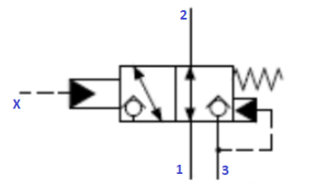
All ports accept fluid under pressure and can be used as per Normally Open or Normally Close function:
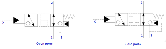
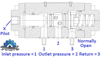
Normally Open
- Pressure Line PORT1 (Inlet)
- Actuator Line PORT2 (outlet)
- Discharge Line PORT3 (oil return)
- Pilot x
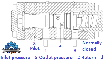
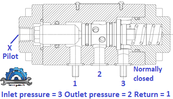
Normally Close
- Pressure Line PORT3 (inlet)
- Actuator Line PORT2 (outlet)
- Discharge Line PORT1 (oil return)
- Pilot X
Directional poppet valves consist of a housing bore, which one or more suitably formed seating elements (moveable) in the form of balls or cones, depende where are situated. When the operating pressure increases the valve becomes more tightly seated in this design
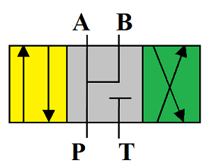
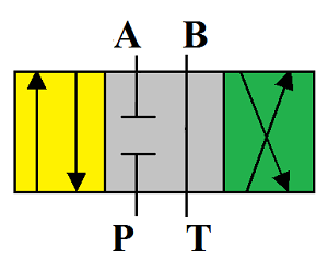
Below the drawing with internal check valve
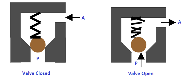
In general, is like a check valve, it allows free flow of fluid only in one direction (P to A), a soon valve will open (hydraulically), the Port P and A will comunicate with each other, exactly what shows the figure above. In the other direction the valve is closed by the ball poppet.
Note: the fluid pressure from A pushes the ball to its seat and hence the flow from the port A is blocked.
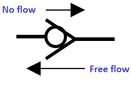
The symbol for this type of design is same with a check valve (see photo below).
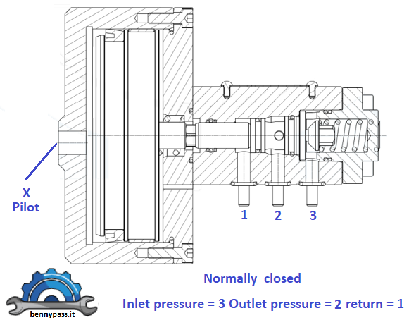
There are also options like REVA Oleodinamica where poppet valves are available in several options. We chose Reva company because are reliable and robust poppet valves, they are installed in very critical equipment like HIPPS valves or shutdown valves. For the datasheet click here for Reva or here for Parker (see photo below from Reva)
Type A (Internal Pilot)
Type B (External Piloting)
Type C (External Piloting -Low pressure)
For more information about poppet valve, write your question This email address is being protected from spambots. You need JavaScript enabled to view it.
Advantages
- Unlike spool valves, poppet valves open an immediate flow path to the outlet. This results in a fast response time.
- Poppet valves only open as much as is needed by the flow going through it, traveling a minimum distance to do so, which increases its response time.
- The large surface area that is essential for poppets results in a higher flow rate. Poppet valves require small actuation strokes, which allows for shorter switching times.
- The large surface area that is essential for poppets results in a higher flow rate
- Poppet valves require small actuation strokes, which allows for shorter switching times.
- The fact that poppets can be used with any material also makes them very inexpensive and easy to use.
- Other benefits of poppet valves are that the axial sealing used is resistant to soiling, and they do not require lubrication.
- Poppets are also beneficial when it comes to longevity, as less wear on the internal seals leads to a longer product life.
- Poppet elements do not stick even when left under pressure for long periods.
- May be used with even the highest pressures, as no hydraulic sticking (pressure dependent deformation) and leakages occurs in the valve
- No Leakage as it provides absolute sealing (< 1 drop per minute).
Disadvantages
- Due to the constructional constraints, poppet valves are not advantageous when it comes to the relationship between space and flow.
- The disadvantage of poppet valves is that, as the poppets shift from one flow path to another, hydraulic or air is free to travel in any direction. This is known as “Crossover.”
- With pressure-independent models, poppet valves offer a lower flow than Spool Valves.
- Poppets are typically not recommended for vacuum conditions.
- Depending on the design of the poppet valve, the switching of positions can lead to overflowing between channels. This may cause unnecessary leakage and noise.
The Spool Valve
Hydraulic directional spool valve is a relative motion between the valve spool and valve housing, is used for controlling fluid-flow direction of actuator motion(movement). Also, can select alternative hydraulic oil control circuits, achieve logic control function. The hydraulic spool valves target is to reach different mechanical movement of actuator, like to release pressure, stop or redirect the pressure or flow in hydraulic systems.
The key part of hydraulic spool valve is spool, a spool valve function depends on the spool type, using different spool type in the middle of valve housing position will achieve different purpose in hydraulic system, therefore, appropriate function spool in middle position must be selected as per its feature during the design of hydraulic systems. There are various type of spool, like “E”, “J”, “H” etc.
The spool valve consists of a spool which is a cylindrical member that has large diameter lands machined to slide in a very close fitting bore of the body valve. The spool valves are sealed along the clearance between the moving spool and the housing. The degree of sealing depends on the size of the gap, the viscosity of the fluid and especially on the level of pressure. Especially at high pressures (after 350 bar) leakage occurs extent and shall be not underestimated because can determining the system efficiency. The amount of leakage is primarily dependent on the gap between spool and housing. Therebefore, as the operating pressure increases the gap must be reduced or the overlap length increased. For this reason it is necessary to identify the proper spool valve for your aplications.
As you can see from the photo above, the spool moves to different positions for match the respective communication ports. The red arrows indicate the excitation of the solenoids which are a fundamental part of a spool valve.
There are many models for most varied applications, below some of these
Hydraulic Spool Valves Diagram (ISO common used)
The symbols that represent hydraulic components typically shows with following characteristics:
- Function
- Actuation and return actuation methods
- Number of connections
- Switching positions
- General operation principle
- Simplified representation of the hydraulic flow path.
Characteristics that are not included in order to simplify the circuit are:
- The size or dimensions of the component
- Manufacturer of the parts
- Operation of the ports
- Physical details of the elements
- Unions or connections other than junctions.
The purpose of this refresher is to help to identify some of the universally basic symbols that you can use to create your own drawings and read drawings from other sources.
|
Spool Valve type A
|
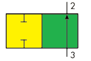
2/2 way valve - Two closed ports in the closed neutral position and flow during actuated position |
|
Spool Valve type B
|
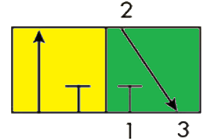
3/2 way valve - In the first position flow takes place to the cylinder. In the second position flow takes out of the cylinder to the exhaust ( Single acting cylinder) |
|
Spool Valve type C & D
|
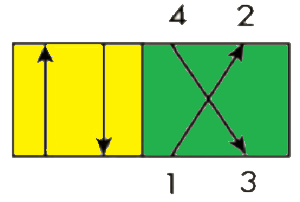
4/2 way valve - For doubke acting cylinder all the ports are open |
|
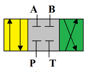
Spool Valve type E
|
In the neutral position , all oil ports closed, no flow .
Functional characteristics:
- The inlet and outlet ports of device are closed, hydraulic actuator can be fixed in any position, no movement or rotary further even if there is external force on it. Therefore, the E spool type cannot be used with the hand mechanism actuators.
- During operation (start-stop), the system remain stable because the returna channel is filled with full oil which may have a dampening effect. When the pressure starts pushing actuator to move, the speed is not too fast due to the influence of oil resistance, it is a big hydraulic shock caused by braking movement inertia.
- The pressure cannot be unloaded in pump chamber.
- High precision of spool switching position.
|
|
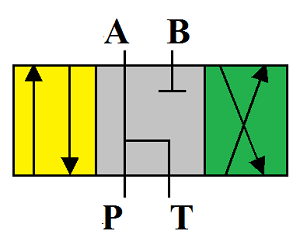
Spool Valve type F
|
In the neutral position, P port is connected to A and oil return port T, the B oil port is closed.
Functional characteristics:
- Pump is able to unload pressure.
- Different working characteristics (switching two directions).
|
|

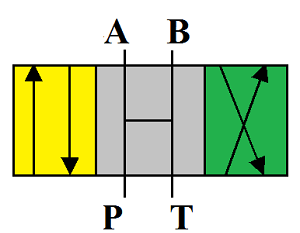
Spool Valve type G
|
In the neutral position, A, B oil ports are closed, P and T oil ports are connected.
Functional characteristics:
- The working actuator allows to stop stably, due to A and B ports closed.
- Hydraulic pump can unload pressure.
- Not available for hand operation actuator.
- Smooth start and stop working process.
- Large hydraulic impact because of inertia when switching.
- The G spool type is used for pump unloading and cylinder locked in hydraulic oil circuit.
|
|
Spool Valve type H
|
In the neutral position, all oil ports are open, no pressure.
Functional characteristics:
- The inlet port P, return port T and work oil port ports A, B all connected, the hydraulic actuator is in a floating state, movement or rotary can be made if there an external force on it, therefore, the H spool type can be used in hand mechanism actuators.
- The hydraulic pump can load the pressure.
- There is an impact from stop to start. The return oil flows to oil tank when the actuator stops working, there is no dampening effect of H spool type, the spool is more stable than E type when spool switching.
- For double-acting cylinder, due to effective area on both sides of the piston is not equal, so the H type valve can not hold the cylinder piston in the stopped state.
|
|
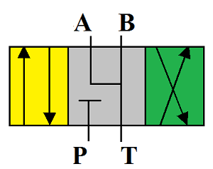
Spool Valve type J
|
In the neutral position, the inlet P port is closed, oil ports of A, B and T are connected.
Functional characteristics:
- Because oil ports of A, B and T are connected, operation actuator is in the floating state, movement or rotary can be made if there is an external force on it, therefore, the J spool type can be used in hand mechanism actuator.
- There are some hydraulic impact from stop to start, switching performance is between E spool type and H spool type.
- Pump is unable to unload pressure.
|
|
Spool Valve type M
|
In the neutral position, T port is closed, and P, A, B oil ports are connected. Functional characteristics:
- Double pole & double-acting cylinder with equal diameter, both sides of cylinder piston keeps balance in hydraulic pressure, operation actuator stops stably. The M type can be used in manual operation actuator, not available for single pole or diameter not equal to double pole and double-acting cylinder, where operation actuators will not be at static condition to compose differential hydraulic oil circuit
- Relatively stable stop and start operation, smooth switching for hydraulic pressure in two chambers of cylinder.
- Hydraulic pump is unable to unload pressure.
- Little switching space position than H spool type, widely applications.
|
|
Spool Valve type U
|
In the neutral position, P and A oil ports are closed, the B oil port connects to T oil return port.
Functional characteristics:
- Pump is unable to unload pressure.
- Different working characteristics while switching two directions
|
Before selecting hydraulic directional spool valves, it must be sure to choose appropriate spool valve in neutral position as per requirements of hydraulic system.
- Design pressure unloading circuit by spool function in neutral position to achieve energy savings. When H, F and G spool type in neutral position of 4way, 3postion directional spool valve, the oil fluid from pump returns to oil reservoir directly to complete unloading hydraulic oil circuit, which allows pump to work under no load or a very small output power to achieve energy saving.
- Utilize the neutral position spool function to design the hydraulic brake or block circuit to stop the actuators operating at any desired position, and the hydraulic brake circuit to prevent the actuators from moving due to external influences. Select the G or E spool type for the hydraulic spool valve to cut off the inlet fluid flow and quickly stop the actuators from moving when the spool is in the center position
- Achieve the floating state of the actuator by using H or J spool type. For example, the slewing mechanism of a hydraulic crane works under high load; the inertia force generates a strong hydraulic shock if the hydraulic power is switched too quickly. Therefore, the problem can be solved by choosing H or J spool type for the hydraulic spool valve.
Below the drawing that include also solenoids for the movement of spool valve
Advantages
- The main advantage of spool valves is that the spool movement is not affected by fluid entering the valve at any working port. The pressure is always applied to two equal opposing areas. As a result, the pressure cannot move the spool because they are cancelled out.
- Spool valves can shift either manually, electrically, mechanically, pneumatically, or hydraulically with the same force, independent of the operating pressure inside the valve.
- Low-force solenoids can be used in conjunction with spool valves, due to their easiness of movement via mechanical friction and light springs.
- The spool valves are able to be used in vacuum operations.
- They can also be employed in high and low pressures as selector valves. Moreover, they can be used to lock pressure downstream.
Disadvantages
- The metal-to-metal slide fittings can result in fluid bypassing the seal, so results in leakage.
- The actuator will lose position if outside force is applied. This creates inefficiencies in the form of wasted energy and heat.
- The delay is small—only a few milliseconds—but may cause a problem if the cycles are very fast and/or if there are several valves shifts per cycle.
- A time delay also occurs if the spool shifts back to the end of its stroke.
- The spool valve moves more than it needs to for the required flow. As a result, it takes up more time shifting back to center or to the opposite flow path.
- When several valves are involved, this significantly slows down the cycle time.
Conclusion
The accompanying table is a valve selection aid. Both spool and poppet valves come with advantages and disadvantages, but the one that best fits your application will depend on your operating conditions. One must consider, for example, if low leakage values and dual pressure operation with vacuum and ejector pulse are your design priorities. Or if you are more concerned with high operating pressures, some leakage may be allowable. Better understanding of your operating conditions will help guide you to choose the right valve for the job.
www.bennpass.it
|