
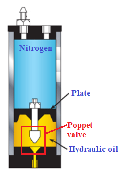
Hydraulic Piston Accumulator (working principle) Introduction The fluid chamber is separated from the gas with a floating piston with gas-tight seals. The gas chamber is charged to a predetermined pressure using nitrogen or another compressible gas (normally nitrogen). This gas charge causes the piston to move down. After the pre-charge, hydraulic fluid is pumped into the hydraulic fluid port. As fluid enters the accumulator, the piston is pushed up, thereby compressing the gas and increasing its pressure. The gas pressure remains applied to the hydraulic fluid through the piston. The piston moves freely between the lower-end cap and its upper position, ensuring that pressure on the gas and the hydraulic fluid is always equal. (In practice, friction between the piston seals and the cylinder wall will create a small pressure differential, which is usually less than 1 bar with appropriate accumulator design and seal selection.) Note: With a difference of 1 bar between both faces of the plate surface and with a diameter of 200mm will be very strong power (kg * cm2) Accumulators can reduce fluctuations in hydraulic lines due to sudden changes in hydraulic flow rate. They also provide a short-term energy source for high-rate tests by providing additional hydraulic flow for short periods to meet irregular peak demands. Like a capacitor, accumulators filter out pulses in the hydraulic fluid to provide steady hydraulic pressure.
Working Principle
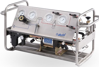
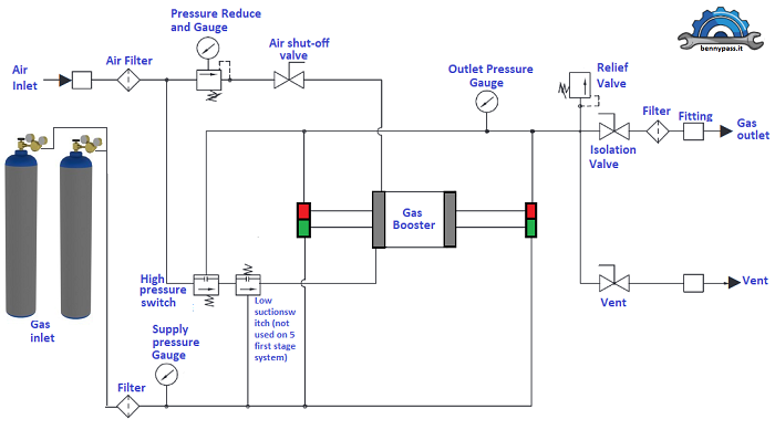
The piston accumulator works at high pressure of up to 15000 psi. Even if it is a good accumulator, there are problems and not a few. Material required for the pre-charging When the work pressure is higher than 500 bar or more, there is no type of nozzle or special tools in order to communicate with the cylinder. The maximum working pressure of the nitrogen cylinder is 300 bar (rating of the cylinder), so in this procedure will use the pneumatic booster pump, which will raise the pressure from 300 bar till the pre-charging of the hydraulic cylinder (internal piston), which is 1000bar In this case, we will use the metal/metal or cone/cone sealing technology without any O-Ring or Teflon (see Figure 2 below) As we said previously, no transportable cylinder can store 500 bar of nitrogen pressure. The maximum working pressure of a cylinder should be 300 bar only (subject to exceptions) For this pre-charge, we will use a booster pump to raise the pressure from 300 to 700 bar, which is the pre-charge nitrogen pressure of the cylinder (piston). Figure 3 below shows the Pneumatic booster pump (Haskel). Costly pump, but it will never damage, or if it gets damaged, the spare kit is available. The booster pumps or gas/hydraulic pumps are also available here. We also supply fittings, reductions, all for high pressure, and all certificates. For more details, go to purchasing section.
Many models are available; Parker or Maximator, or whatever, it doesn't matter, are all reliable and certified. Maximator is the reference in this guide. Material and tools that are required
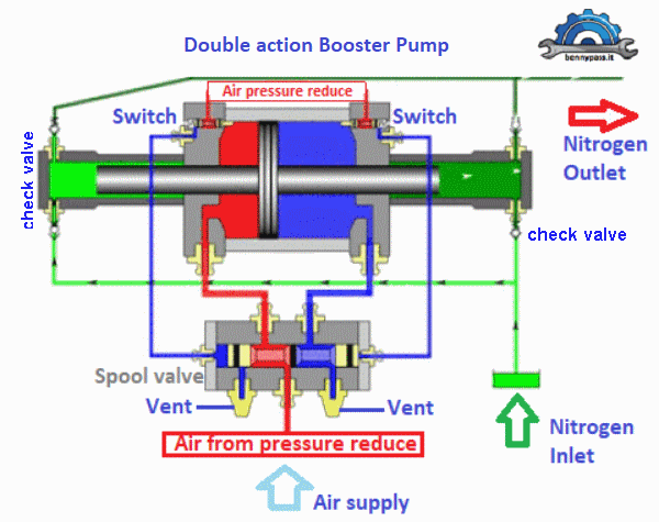
booster pump diagram
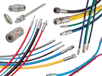
As you can see from the diagram in Figure 3 above, the double-effect booster sucks gas from two sides and sends it from two sides (see figure 4 below). Note: The pump is directly proportional between the inlet and outlet pressure. For example, 30 bars in suction are 300 bars output, or 10 bars in suction are 100 bars in Output, Etc. Read the booster manual (1: 10 - 1: 30 - etc.). Flexible Hose and Fittings The flexible hose is a fundamental system part, especially for high or very high pressures (in output). The flexible hose must be rigorously for high pressure (tested and certified and indicated by the label directly on the flexible hose itself), including the fittings (for more details, see Figure 5 below) Never mix any fittings between two flexible hoses, or make something handmade. Depending on the order, the flexible hose fittings have a particular thread size (JIS, BSPP, SAE JIC 37° or 45°, PARKER/AUTOCLAVE). Those who manage the fittings, and flexible hose connections, must have an in-depth knowledge of all types of fittings (see Figure 5 below) When finalizing an order, everything must be considered (rating, Temperature, size, material, fitting connection, bursting pressure) must be considered.
Bottles Nitrogen Cylinder The Nitrogen cylinder, as explained before, maximum working pressure is 300 bars which is the maximum pressure acceptable for the cylinder itself (transportable cylinders). The cylinder must also include the pressure regulator, as in Figure 3 above.
Hydraulic Circuit Inspection
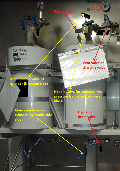
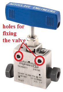
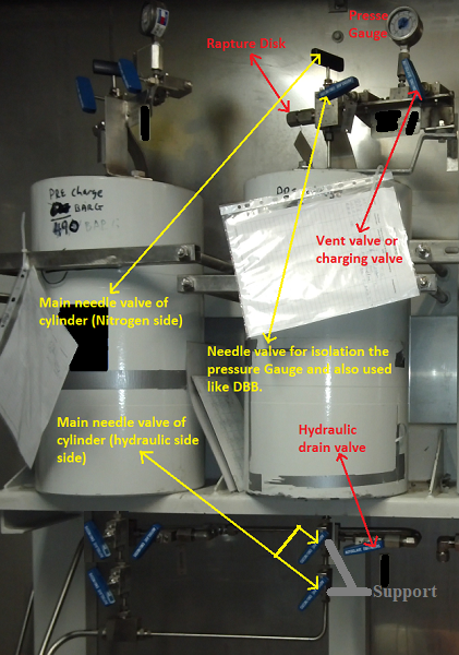
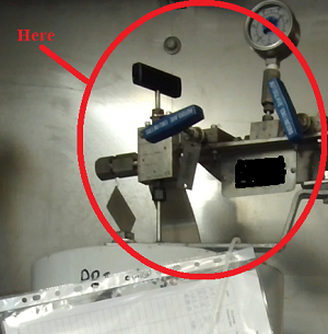
Unfortunately, Figure 6 above shows a poorly done circuit (in terms of safety). To inspect the pre-charging of one accumulator, all others, including the primary circuit, must be depressurised because there is no double safety valve. When the pressures are very high, the second isolation valve must be mandatory, especially where the frequency of maintenance is too high, as the accumulator test pressure. The second significant error is that: the valves are without fixing support. According to PARKER procedure, the valves must be fixed with their supports (mandatory), especially when the valves are cone-to-cone seals and can easily unscrew. For example, operating the valve under pressure is necessary, so more force is required. If the valve is not fixed properly, the force that applies to the valve can be transferred to the fittings because the valve can rotate easily. With 1000 bars inside will be a huge problem. Safety first; for this reason, I highlighted Figure 7 below. For more details, you can see the cone/cone procedure here.
Figure 8 below shows the circuit with double valves and fixing support (as per standard)
Pressure Inspection and Pre-charging procedure
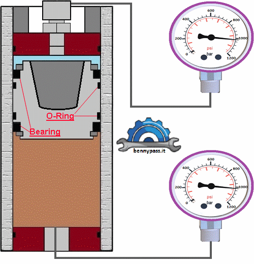
Warning: Careful when opening the drain valve to drain the hydraulic oil. The most important is the pressure gauge which indicates the pre-charge pressure on top of the cylinder (pressure gauge is mandatory on the pre-charge side of the accumulator). Usually, when oil exits from the cylinder (bottom side), the pressure gauge should indicate that the pressure drops because the internal piston/plate moves and increases the internal surface of nitrogen, with the consequence that pressure will follow the pressure of the hydraulic side. If the pressure does not drop, the piston/plate is stacked. Do not continue to drain the hydraulic oil. It could be fatal for those who work near the cylinder. In this situation, (ASAP) must be depressurised the entire cylinder simultaneously on both sides (nitrogen and hydraulic oil side). The next step will be internal maintenance of the cylinder, including the internal Piston. Remember, if the oil is drained from the cylinder with the internal Piston blocked, it immediately creates a space between the Piston and the hydraulic oil. The consequences could be devastating if the DP increases between the nitrogen and the hydraulic side; the Piston will be like a hummer which presses the liquid under pressure. Unfortunately, many serious incidents occurred in the world for this reason. For example: if accidentally, a space has been created between the hydraulic oil and the piston/plate, and for some reason, the DP between nitrogen and hydraulic pressure will increase up to 30 or 40 bars (I don't want to imagine more), the consequence will be that the internal piston/plate maybe will unlock and cause tremendous power that will lift the cylinder itself and break all connecting tubing's and supports and possibly severe injury to the personnel who are close by ( the cylinder can flight from support). To understand the extent of force, it is like a hammer with a surface of 200mm or more (depending on the Piston diameter) which nitrogen push on the piston/plate, and then the piston/plate bump into a liquid which is not compressible (a devastating force). More space increases, and more power it will be. During regular operation, the DP created between the oil and nitrogen sides is only 1 or 1.5 bar (max). The force of 1 bar (DP) that pushes a surface of 200mm will be already strong, imagine if the DP becomes 100 bar, and the piston/plate is stacked and remain 10cm space between the piston/plate and hydraulic oil (more I don't want to imagine). For this reason, you should never take risks. If the piston/plate moves and is confirmed by the pressure gauge on top of the cylinder that pressure drops, in this case, continue to step 4. Suppose the pressure of the nitrogen side will not decrease during the drainage of the hydraulic oil from the bottom of the cylinder. In that case, there is only one solution: the cylinder must be isolated and depressurized simultaneously between the nitrogen and hydraulic oil sides and then given to maintenance. Usually, before putting a new piston cylinder or one under maintenance in service (under operating pressure), it should be tested with a few bars, as explained above, to understand if there are no problems inside. Remember, when draining the hydraulic oil, the two pressures between nitrogen and oil must always be the same or a difference of a few bars.
Figure 10 - Piston Accumulators
Internal maintenance of piston Accumulator The procedure for opening an accumulator depends on the manufacturer. Each manufacturer has its policy, including special tools. The files below (PDF) show the most important accumulator companies. Above there are the most important companies. To open a piston-cylinder is very simple; follow the instructions given by the various manufacturers. However, highly qualified personnel must be present for the supervision. The steps are few.
Approximate accumulator calculation The size listed for an accumulator refers to its total nominal gas volume, not its fluid capacity. The volume of fluid an accumulator provides for a particular application depends on the system’s differential pressure. Manufacturers offer computer programs that may require only the system requirements to determine the correct accumulator size. Because accumulator sizing depends on many variable factors, it’s always best to consult the supplier for specific information about selection and sizing. The amount of fluid volume an accumulator can deliver to a system depends on the application. These are the minimum parameters required to determine the fluid volume and/or accumulator size: Parameters and abbreviation
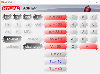
As you can see, to calculate the volume and pressure of a cylinder, there are many parameters, including the external temperature of Nitrogen charging. Luckily sometimes, some programs facilitate the situation, such as the ASPlight provided by HYDAC. The program is elementary and intuitive, considering that HYDAC is a reliable company. Figure 9 below shows the program ASPlight
You can download the manual ASPlight here, and the program you can download here.
Recommendations
Conclusion In many fluid power applications, the driven member of the hydraulic system stops suddenly, creating a pressure wave that travels back through the system. This shock wave can develop peak pressures several times greater than normal working pressures. It can cause objectionable noise or even system failure. An accumulator's gas cushion, located correctly in the system, will minimize this shock; this is why the accumulators are a significant part of a circuit. Choosing the suitable accumulator is of fundamental importance because it solves problems such as fluctuations or stores hydraulic oil that can be used when a greater quantity is required. Unfortunately, many accidents happen during the verification or re-charging of piston cylinders. I participated in investigating an incident that took place offshore platform. The internal piston/plate of the cylinder was blocked. The personnel did not know how to work it and decided to drain the hydraulic oil and leave only the nitrogen pre-charge, hoping that the piston would move (in fact, it moved). As soon as a DP of almost 100 (or more) bar was created, the piston/plate unlocked and had no liquid nearby. Unfortunately, what I explained in this article happened. A cylinder of almost 300 litres has risen by one meter, breaking all the tubing (high pressure) and supports to smash its container, and the hydraulic oil came out under pressure. Fortunately, the two people who worked were left unharmed. The weight of the cylinder is 550kg. It went well, very well; it could have been worse, a lot worse. To avoid such problems, we always suggest that experienced personnel must work on these accumulators. Working on accumulators is very dangerous, especially if the staff are not specialized. For any support, you can contact us directly on the website. For any questions, you can send an email to the site. We supply accumulators according to your request. All fitting connections for low, medium or high-pressure are included in the accumulators.
|


+(39) 347 051 5328
Italy - Kazakhstan


09.00am to 18.00pm
About
We offer the best and economical solutions, backed by 27+ years of experience and international standards knowledge, echnological changes, and industrial systems.
Our Services
Marketing Materials


Marketing Materials1


