
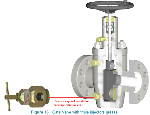
Working principle of Grease Injection on Gate or Ball Valves Introduction Grease injection on high-pressure gate/ball valves works by using a special gun to force pressurized sealant/lubricant (grease) through a fitting into internal channels, filling the space between the sealing surfaces (ball/plug and seat) and stem packing, creating a hydraulic seal, reducing friction, preventing leaks, and washing away debris, effectively lubricating and repairing the seal under pressure for smoother operation and extended life. Working Principle API 6A API 6A gate valves are designed to achieve a metal-to-metal seal between the gate and seat. In some cases, the seal surfaces can be damaged due to insufficient preventative maintenance, poor choice of service lubricant, arduous operating conditions or a combination of all three. The first thing ever for perfect greasing should be removing the old grease from the body valve and packing. Let's take the gate valve as a reference since it is the most subject to periodic greasing because they seal metal to metal. There are three types of gate valves with single, double, or triple injection grease, figure below shows body valves with a single and double or triple injection grease.
The difference is clear, valve equipped with three grease injectors (see Figure 1), it is possible to lubricate the internal gate and also the stem packing, while the one with a single injector grease (see Figure 2) can only lubricate the stem packing only, or, in some cases the single grease gun can lubricate the gate only. If the valve installation is expected where there is a lot of dirt or where the DP between upstream and downstream is very high, the valve with three injection greasers is the right solution. Unfortunately, missing out on quality for a slight discount isn't considered smart. In some cases, requires to open internal body to replaced the gate, set, etc., and spending double the money, with the consequence that it does not guarantee opening or closing in case of emergency. The manufacturer doesn't support specific projects; success depends entirely on effective project engineering. For this reason, it always requires a good engineer with a lot of experience to choose the proper valve based on the process condition. The gate valve, as explained above, is used for cutting flow under perfect sealing, which other valves cannot guarantee. For this reason, its functionality must be perfect. To work perfectly, the high-pressure gate valve should be linear with an internal body valve to slide smoothly on the two seats. If the gate valve is used as On/Off valve (Emergency Blowdown Valve), it means that upstream there is pressure and downstream is a vent, and then the force pushes to one side only resulting in the gate tilting away from the applied pressure" or "causing the gate to tilt to the opposite side of the pressure, and during activation (open/close), the valve can gets stuck.
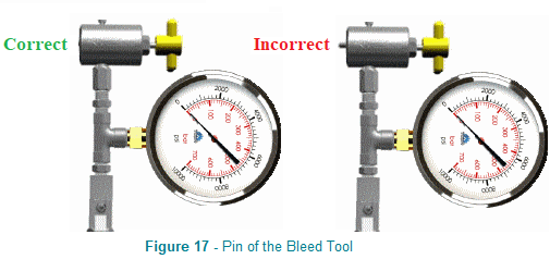
Sometimes this type of valve gets stuck (not operating) due to obstruction from old grease or process dirty. This issue compromises the pressurization of the entire cavity. Therefore, the gate will push to one side and create extra friction during movement. In this case, the best solution before opening the body valve, wash the valve with alcohol or methanol and then grease it. A good idea to understand if the self-balancing system works is to apply a pressure gauge on the grease nipples and close the valve. When the line upstream is pressurized, the pressure should also increase on the pressure gauge (grease nipple). This means the cavity gets pressurized, and the balance system works fine. If pressure will not increase on the pressure gauge means the hole or labyrinth is plugged in. This is the best way for the troubleshooting Type of Injector grease The grease injection phase is critical because it is dangerous, especially when it is required under pressure. There are a lot of special tools which are supplied by different companies. Figures 6 to 14 below show the most important ones.
All references have been taken from the parker catalogue because it is one of the most reliable companies in the world. As you can see from the Figures above, there are a lot of models. While, nipples go on valves, they're also on bearings, joints, etc. The core types are defined by shape/angle, not just being "on the body. Typically, two are used for this scope, as shown in Figures 13 and 14 below
Sometimes, for production requests, the injection grease is performed under pressure inside the body valve. All is possible, but the risk it's high, especially when corrosive liquid or gas such as H2S with high concentration is present.While high-pressure greasing is discouraged in this case, a minimum amount of pressure is necessary to flush out the old grease using the specialized tool, so monitor for resistance and use pressure-relief fittings if possible to prevent seal damage. Procedure to inject grease of a Gate Valve Recommendation: The first thing before any other actions is to use the special tools supplied by the valve manufacturer or identify the correct grease injector and order. The working pressure, and temperature, must be considered as a priority for the type of grease.
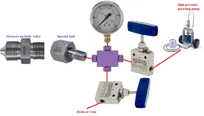
This application is one of the safest because the tool is screwed directly into the Greaser. Suppose greasing fails during grease injection (under pressure) due to a damaged internal check valve. In that case, more safety can apply a shut-off valve in case the Greaser fails. This can happen quickly and easily, especially when the Greaser is not used frequently and the internal condition is unknown. For this, we always recommend if it is decided to grease a valve under pressure, the shut-off valve and a pressure gauge are mandatory (see Figure 20 below)
Figure 20 above shows how to install the tools and grease a gate valve under pressure. The Installation of pressure gauges and valves is used to prevent failure from greasers (leaks), which can happen very quickly. The shut-off valves are used to isolate the Greaser during grease injection. The drain valve always remains closed and will open only in case the injection grease phase is completed and depressurize the line. The pressure gauge is used to clarify if the internal check valve of the Greaser is closed properly (with the drain valve closed should not increase the pressure on the pressure gauge). If everything ok, it is possible to remove the tool and install back the Cap. If the greaser leaks (pressure doesn't drop from the gauge) should depressurize the line (Production line) and change the Greaser.
For more details, see the video with Double and single Greaser Double Injection
Single Injection
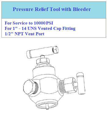
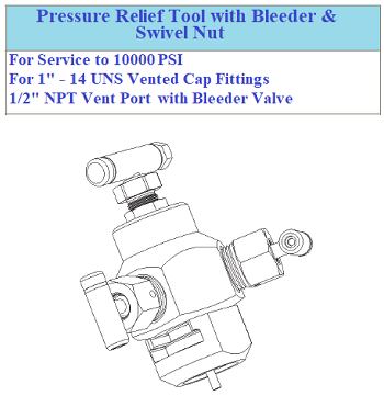
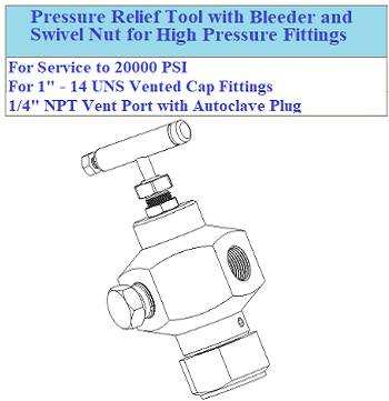
Note: However, removing the grease nipple cap under pressure remains a risk not to be underestimated Figures 21 and 22 below show the second type of Greaser and tool (Giant)
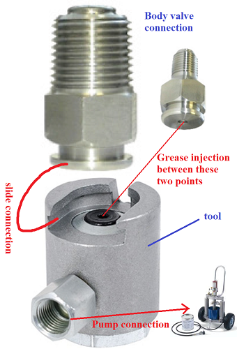
As you can see from Figure 21 and 22 above, the giant nipple does not have a proper fixing system but a system with a slide which join the circular head of the Greaser with the tool. The seal is obtained from the grease itself under pressure. Even if these types of injections many companies they classify it for high pressure, I doubt it for the simple reasons described below:
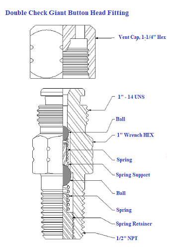
Conclusion The greasing of a valve, even if in reality it is simple and intuitive, hides many unknowns. This is why we always prefer an isolation valve, even when the pressure is zero. Sometimes, we are sure there is no more pressure upstream and downstream after depressurizing the valve. Unfortunately, sometimes this is not the case. The internal cavity of the valve can remain under pressure (trapped pressure) due to the dirty inside, even after depressurization of the body valve. Suppose the internal labyrinth or the equalization hole is blocked due to dirt inside (like Pyrophoric, etc.). In that case, the only way to depressurize the cavity of a gate valve is from the Greaser. This is the reason why we always recommend before replacing the Greaser or opening the valve bonnet to replace the packing, connect the bleed tool to the Greaser, which includes the pressure gauge, and check if there is any pressure inside the cavity. It has already happened in a field where the personnel had depressurized the valve to replace his Greaser due to the internal check valve leaking (375 bar). Unfortunately, the cavity was under pressure due to Pyrophoric, which obstructed the depressurization of the cavity (labyrinth dirty). As soon as the Greaser has been removed, immediately the acid gas gets out. Luckily the personnel was with breathing apparatus, in different was a disaster would happen. The internal labyrinth is used for pressurizing the cavity and equalization the internal gate. For more detail,s see Figures 3 and 4 above).
Recommendations Working with grease injection involves a lot of risks for the personnel. Many incidents are caused by injection grease. The grease under pressure can break the skin of a finger or arm and penetrate inside with the risk of infection or even amputation of the finger or arm if not aided in time. In injection injuries, prompt diagnosis and immediate aggressive surgical intervention are necessary to save the patient's digit/limb. Patients should be informed about the severity of their injury, its potential complications and the multiple surgical procedures that may be required for a satisfactory functional result. High-pressure injection injuries result from the improper operation of equipment that achieves ejection pressures of their contents sufficient to breach the human skin1. This is why the correct tools must be available and not as hearsay, maybe for the other valves or the other scope. These injuries are uncommon, with an estimated incidence of one in 600 hand injuries presenting to an emergency care unit2. They occur predominantly in young men and are primarily occupational injuries. Most injuries affect the non-dominant index finger and usually happen due to inexperience in operating the high-pressure equipment, inappropriate use, insufficient training, carelessness, fatigue at the end of the shift or rupture of the equipment. The most commonly injected substances are paints, paint solvents, grease, and fuel oil (paraffin oils, diesel oil, gasoline), but there has also been reported injection of water, air, and cement. Never touch with hand the pump or grease nipple under pressurization. The new technology of pumps provides a remote control which can operate the pump from far without personnel near the injection.
|
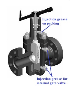
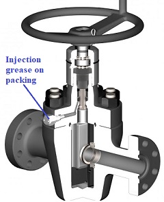
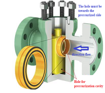
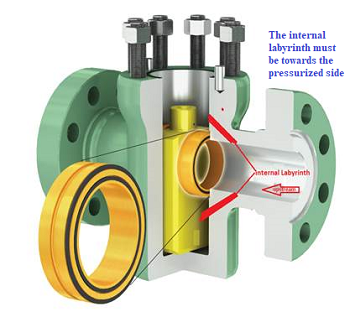
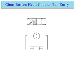
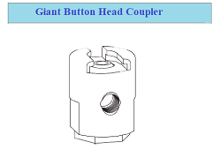
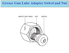 Figure 8 - Grease Gan Lube Adapter
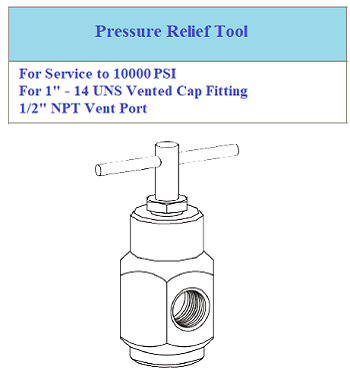
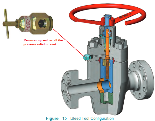
 Once the stem is placed on the valve, rotate the clockwise slowly handwheel to push the ball in order to open the port between the cavity and the vent tool. Drain the cavity of the valve until all the old grease and sediments from the vent tool exit. Usually, the drainage should be done from both sides of the body valve (if available double grease nipples). This is the correct procedure for removing all dirt mixed with grease inside the cavity. A clean cavity condition reduces the extra friction of the gate valve. Removing the sediments inside the cavity is essential to avoid any extra friction on the gate valve. For more details, see Figures 15 and 16.
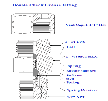 Figure 18 -
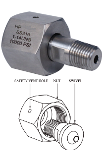


+(39) 347 051 5328
Italy - Kazakhstan


09.00am to 18.00pm
About
We offer the best and economical solutions, backed by 27+ years of experience and international standards knowledge, echnological changes, and industrial systems.
Our Services
Marketing Materials


Marketing Materials1


