
Working Principle of Partial Stroke Introduction Partial-stroke tests (PSTs) of emergency shutdown (ESD) valves improve safety instrumented system (SIS) performance; monitor these critical valves to ensure the system’s ability to shut a process down in the event of an emergency. A partial-stroke test (PST) is a procedure/test used to stroke emergency shutdown (ESD) valves partially. It also is referred to as a partial-valve stroke test (PVST). The alternative is a full stroke test (FST), where the valve is completely (100%) closed/opened during the test; the typical range of a PST is 10% to 20% of valve movement. The setpoint for the PST depends on the process upset it will create, and thus, the sizing of the valve and manufacturer recommendations. A PST is necessary to achieve higher safety integrity level (SIL) (typically SIL3) where probability of failure on demand (PFD) calculations of the safety instrumented function (SIF) loop do not achieve the desired targets by any other means. PST increases the SIL, but because the implementation is expensive, it should be a last resort to achieve the SIL level targets. This means all other means have been tried and are not feasible, or the cost to achieve the desired SIL target is prohibitively high. The PST requirement arises in plants where turnaround time (TAR) is high, and it is not possible to do a full stroke test for an extended time.
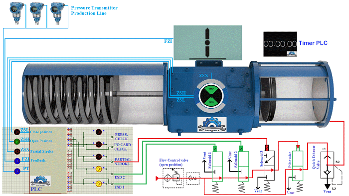
How can work the Partial Stroke The standard of Partial stroke on board an actuator is equipped with 3 solenoids on the panels (A, B, C), which C is normally open, means the air or hydraulic oil passes without the solenoid being energized, while A, B are ESV (Emergency Shutdown Valve) and they used for close or open valve, in this case are normally closed, means the air or hydraulic oil pass through only if energize them. Below the photo with the drawing:
The standard procedure the Partial stroke has to work only with the solenoid C because in the event of coil fail, or the fuse breaking, the solenoid returns to the normally open condition and then the actuator / valve reopens, without close the valve with abnormally situation, consider that are critical valves. Closing a production by half sequence is very dangerous. The standard actuator is equipped with three limit switch and are: ZSH (limit open) ZSL (limit close) and ZSX (limit partial stroke). Sometime the ZSX limit switch which is the limit partial stroke it is replaced with the position transmitter FZI or EZI. below the figure with all details
Working Procedure step by step
Conclusion Below an video with all Partial Stroke details (Working Principle)
In my opinion where existing two solenoids only and both are fail close It is not advisable to perform the partial stroke , and where are installed three solenoids and one of them is fail open, should be using as Partial Stroke only the fail open.
www.bennypass.it |


+(39) 347 051 5328
Italy - Kazakhstan


09.00am to 18.00pm
About
We offer the best and economical solutions, backed by 27+ years of experience and international standards knowledge, echnological changes, and industrial systems.
Our Services
Marketing Materials


Marketing Materials1


