
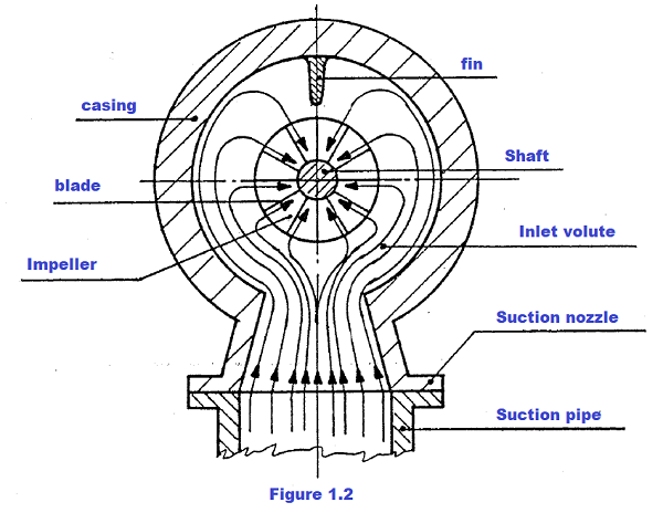
Compressor Gas Path Gas is drawn into the compressor through a sug tion nozzle and enters an annular chamber (inlet vo- lute), flowing from it towards the center from all directions in a uniform radial pattern (see fig. 1.2) At the opposite side of the chamber from the suction nozzle is a fin to prevent gas vortices.
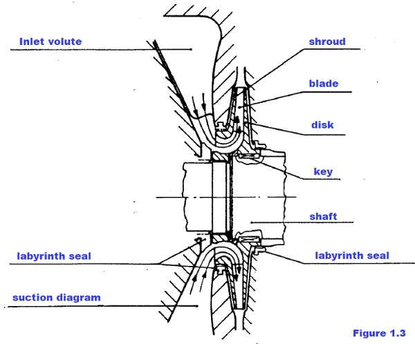
The gas flows into the suction diaphragm and is then drawn by the first impeller (see figure. 1.3)
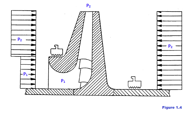
The impellers consist of two discs, referred to as the disc and shroud, connected by blades which are shrunk onto the shaft and held by either one or two keys. The impeller pushes the gas outwards rais- ing its velocity and pressure; the outlet velocity will have a radial and a tangential component (see section 5 for further details). On the disc side the impeller is exposed to discharge pressure (see fig. 1.4) and on the other partly to the same pressure partly to suction pres— sure. Thus a thrust force is created towards suction
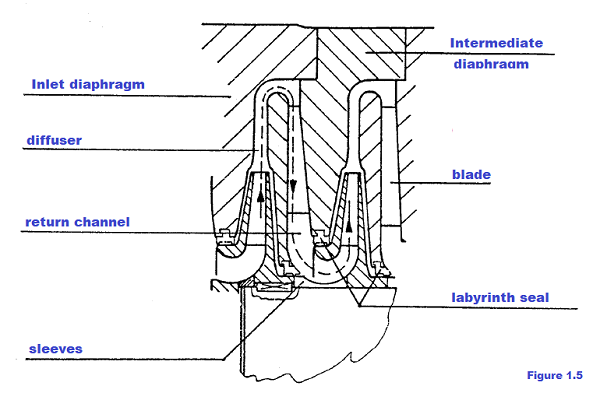
The gas next flows through a circular chamber (diffuser), following a spiral path where it loses velocity and increases pressure (due to the equation for fluid flow through conduits). The gas then flows along the return channel; this is a circular chamber bounded by two rings that form the intermediate diaphragm which is fitted with blades (see fig. 1.5) to direct the gas towards the inlet of the next impeller. The blades are arranged to straighten the spiral gas flow in order to obtain a radial outlet and axial inlet to the following impeller. The gas path is the same for each impeller.
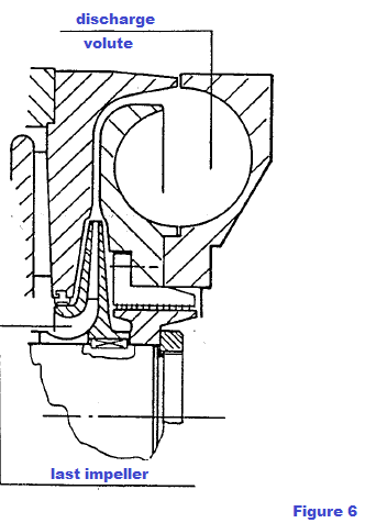
Labyrinth seals are installed on the diaphragm to minimize internal gas leaks (see fig. 1.5). These seals are formed by rings made in two or more parts. The last impeller of a stage (the term stage refers to the area of compres- sion between two cog secutive nozzles) sehds the gas into a diffuser which leads to an annular chamber called a discharge vg lute (see fig. 1.6). The discharge volute is a circular chamber which collects
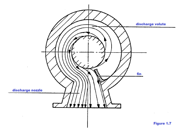
the gas from the external boundary of the diffusers and conveyes it to the discharge nozzles; near the discharge nozzles there is another fin which prevents the gas from continuing to flow around the volute and directs it to the discharge nozzle (see figure. 1.7).
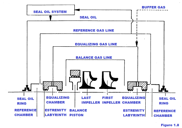
The balance drum (E) is mounted on the shaft after the end impeller (see fig. 1.1). It serves to balance the total thrust produced by the impellers. Having the end impeller delivery pressure on one side of the drum, the compressor inlet pressure is applied to the other by an external connection (bal ancing line, see figure. 1.8). In this way gas pressures at both ends of the
rotor are roughly balanced. To get even closer pressure levels and, therefore, the same operating conditions for the shaft—end oil seals, another external connece tion is made between the balancing chambers (balancing line, see fig. 1.8). Reference gas chambers are positioned outside the shaft—end labyrinths. They are connected to achieve the same pressure as that used as reference for the oil seal system (see fig. 1.8 for a block diagram and section 7 for a detailed description of the seal oil system). In special cases, when the seal oil and process gas have to be kept separate, inert gas is injected in- to the balancing chamber (buffer gas system) at a pres- sure that allows it to leak both inwards and outwards forming a seal.
bennypass.it
|

+(39) 347 051 5328
Italy - Kazakhstan


09.00am to 18.00pm
About
We offer the best and economical solutions, backed by 27+ years of experience and international standards knowledge, echnological changes, and industrial systems.
Our Services
Marketing Materials


Marketing Materials1


