
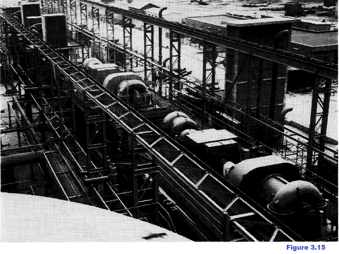
3.6 OXYGEN SERVICE IN METALLURGICAL PLANTS One of the initial premises for the development made in steel production is the possibility of utilizing great quantities of very cheap oxygen (figure. 3.15).
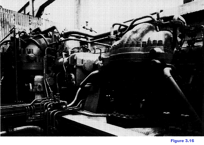
Construction of the most advanced low pressure air separation plants alongside the steelworks has been expanding now for years. The average capacity of these plants has risen from approx. 300 t/d in 1965 to the present 1000-1500 t/d for every unit installed and units are being designed for over 5000 t/d. Another determining element in connection with these new production levels is use of the oxygen centrifugal compressors which are now constructed for large flows and high pressures and are therefore capable of satisfying the most exacting requirements of modern metallurgical plants as well as influencing the choice of requirements. The advantages ensuing from introducing centrifugal compressors also in the metallurgical sector soon became apparent as a consequence of the economy due to the simple operation, modest maintenance requirements and relatively low total cost of installation Around 1965 centrifugal compressors were installed with capacities ranging from 16,000 to 28,000 Nm3/hr and final pressures of 25-30 bars; in recent years centrifugal compressors have come into operation compressing 40,000 Nm3/hr at 40 bars (figure. 3.16)
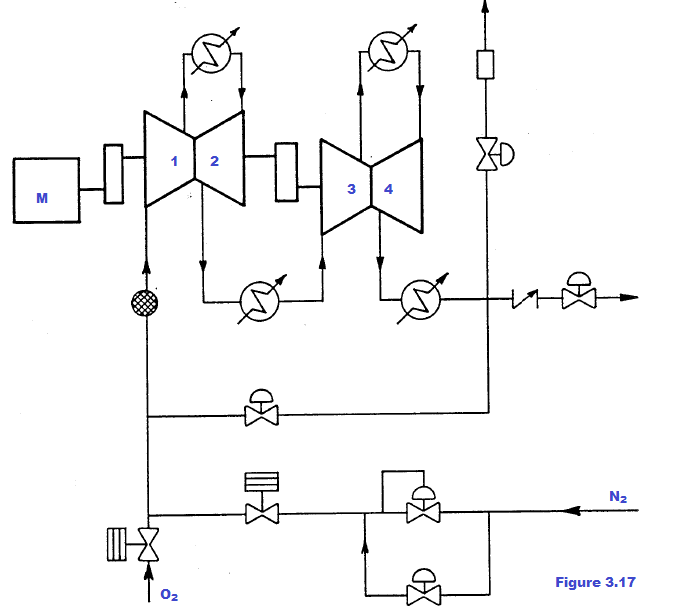
and machines are now being designed for chemical service to reach over 60 bars. These achievements have been made possible by overcoming the problems that principally concern the danger of fire on account of there being 99% pure oxygen in contact with inflam- mable materials including the metal used to construct the compressors. The risks of fire grow considerably when gas pressures, temperatures and flow rates rise and the causes can only be partially directly controlled. The compressors for service in steel works are presently employed at an operating pressure of approx 40 bars, which is the highest pressure standard of those adopted in metallurgical plants for the oxygen distribution network. The gas is generally compressed in four successive stages in two casings (figure. 3.17); the cast iron and steel casings are for low and high pressure respectively, they are horiz0ntally—split and each has balanced opposed stages with sidestream suction nozzles and interstage discharges. The gas is cooled after each discharge in water coolers installed outside the machines.
Figure 3.17 Diagram of oxygen compression from 1 to 40 bars in four compression stages
www.bennypass.it
|

+(39) 347 051 5328
Italy - Kazakhstan


09.00am to 18.00pm
About
We offer the best and economical solutions, backed by 27+ years of experience and international standards knowledge, echnological changes, and industrial systems.
Our Services
Marketing Materials


Marketing Materials1


