
4 . 3 ROTOR The rotor of a centrifugal compressor is made up of shaft, impellers, balancing drum, thrust bearing collar, the coupling hub and some sleeves and spacer rings.
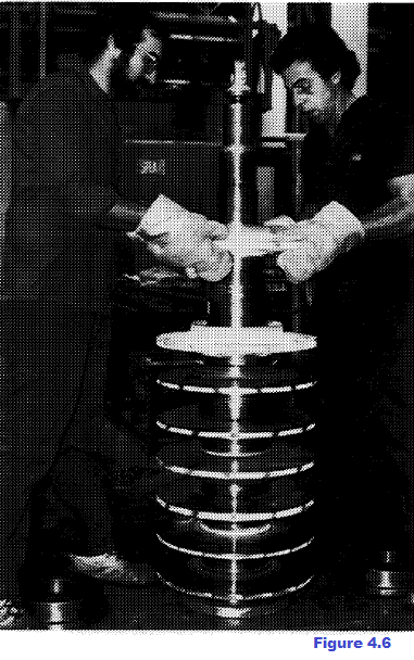
4.3.1 Shaft The shaft consists of a central section, usually with constant diameter, on which impellers and spacers are mounted, and two ends with diameters suitably tapered to house bearings and seals. The shaft is sized to be as stiff as possible (reducing the distance between bearing centers and increasing the diameter according to the flow-dynamic design) to reach the best flexural behaviour The material used to manufacture shafts for any kind of compressor is steel 40 NiCrMo7 UNI. As a matter of fact the mechanical characteristics of this steel are better than generally required for the normal use of centrifugal compressor shafts; that's why other manufacturers use common carbon steels. Steel 40NiCrM07 is very suitable for hardening and tempering; in fact the normal-size shaftsfor centrifugal compressors made up of this steel, undergo entirely this treatment (up to the core) the othensinstead made of common carbon steel undergo it only superficially. Since the aim is at reaching good toughness and ductility, and not very high yield point and ultimate tensile stress value, tempering is carried out at temperature over the normal one, anyhow allowing to reach an ultimate tensile stress over 100 Kg/mm2 and yield point over 65-75 Kg/mm2. 4 . 3 . 2 Imgellers Impellers are shrink-fitted on the shaft (see Figure 4.6).
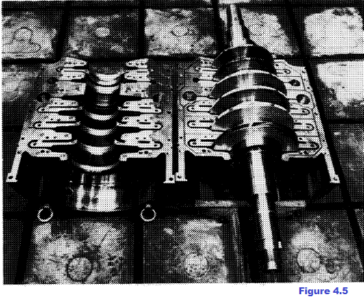
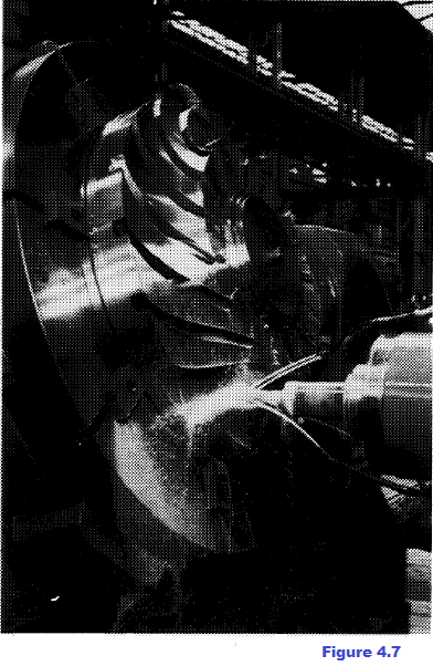
Under the impellers splines are provided to transmit torque. The impellers are interference-fitted not only because of torque transmission, yet to avoid loosening of the mesh under high speed of rotation owing to the stresses due to centrifugal forces, thus preventing also from building up unbalance since the impeller would be no more concentric to the shaft. Impellers may be, structurally, of closed or open type The closed impellers are made up of one hub, a certain number of blades and one shroud. Blading is generally slanted backwards. These parts are joined in different ways; at present Nuovo Pignone apply only welding. Blades are generally milled (see Figure. 4.7) on the hub, (or shroud), then the shroud (or the hub) is internally welded. The blades are milled onto the hub or shroud depending on the impeller shape and, hence, on the possibility for the electrode to get into the channel. If, owing to the narrower width of the impeller, itis difficult to weld internally, external welding is carried out: on the shroud (or hub) near blading and according to its shape, grooves are carried out superficially. Hub and shroud are connected each other by temporary butt-welding. By filling these grooves withweld material, the faying surfaces between blade and shroud are melted thus resulting in a weld. The impeller welding cycle is the following: welding carried out as described before, followed by stress relieving heat treatment, inspection of welded parts, hardening and tempering, removal of machining allowance. The open impellers are different from the closed impel lers as lacking in the shroud. Usually this kind of impeller has tridimensional blades
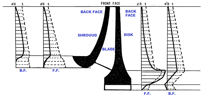
As to the mechanical design it has to be taken into account that the impellers are the most stress- ed elements in a compressor, because the advantage of reducing the stage number leads to higher and higher tip speeds and, hence, stresses. The stress trend in the various impeller parts varies, of course, according to the impeller type; diagrams on pict. 4.8 show a typical situation.
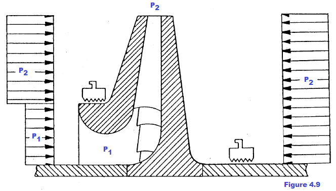
The severest condition occurs during the overspeed test (at 115% of the continuous max. speed). The diagram shows particularly stressed areas on the leading edge of blades. Stress concentrations must be avoided. As a general rule when manufacturingimpellers much care must be taken in finishing their surfaces and designing them, considering particularly the thickness, thekey slots and rounding off the corners. Materials and heat treatments are chosen taking account of the stress due to the centrifugal force (as a function of the tip speed at which the impeller has to run) and the work conditions, such as corrosion, stress corrosion, low temperature etc. To get a good welding result in blades, they have to be made of steel with high mechanical characteristics, yet low carbon content. For all impellers Nuovo Pigngne use KMN COGNE steel, except for particular cases, which is a low-alloy steel fit to low temperature, containing 2% chromium,1% molybdenum and 0.13 to 0.17% carbon. The impeller manufacturers in U.S.A. use steel with higher carbon content, thus getting better mechanical characteristics, but leaving some doubts about quality of welding, as the weld and the area around are subject to intercrystalline corrosion. This is the reason why the British manufacturers call for limits in carbon percentage. The intercrystalline corrosion leads to the relaxation of the metallographic bonds among grains and, hence, to degradation of mechanical resistance. If steel remains at the sensitization temperature (from 400 to 900°C) during the quenching process after heat treatment, as well as during heating for welding, the chromium carbides may precipitate all the more, the higher the carbon content in steel. When impellers handle corrosive media, steel with higher chromium content are used, such as X15C13 (13% Cr); in particularly corrosive areas the chromium percentage in steel is much higher: KXOA2-FNOX steels (from 15 to 19% Cr); besides, if there is some problem in stress resistance along with corrosion troubles, MARAGING steels, series 17% Cr, 4% Ni are used, age-hardened at low temperature. 9%-nickel steel is used for impellers running at low temperature; this content was studied just to get good impact strength up to -196°C. 4 . 3 . 3 Balancing drum During normal operation, inside the compressor a thrust is generated against the rotor, which has to be taken up by the thrust bearing. Such a thrust is mainly due to the pressures acting on the impeller. The Ap produced by the impeller generates, of course, a force in suction direction expressed by the product of Ap multiplied by the area underneath the seal on the shroud. The sum of these thrusts is generally very high and often beyond the thrust bearing capacity. For instance (see Figure. 4.9), let us consider a medium pressure compressor, with 5 impellers, mean Ap for each impeller = 6 Kg/cm2, shaft ¢ = 17 cm, seal Q = 27 cm, the generated thrust is:
Therefore a balancing drum is provided for, after the last impeller; placing its opposite face under suction pressure and sizing its diameter adequately, a thrust is generated from suction to discharge side, such as to balance the thrust coming from the impellers. Balancing is not complete: a residual thrust is thus left, capable of being taken up by the bearing, to avoid any axial unstability of the rotor. Other thrusts are generated besides those described before, such as the thrust caused by the variation of gas moving flow entering the impeller axially and leaving it radially, or such as the thrust resulting from the irregularity of pressure acting on the impeller in high-pressure machine Generally these thrusts are not so high to change the state of things, even if they have to be calculated precisely. It is important instead to take account of the thrust generated by the coupling we shall speak about here inafter. As regards the shape it has to be noted that the width of this drum must be such as to support the whole Ap developed by the compressor: an inadequate sizing of the labyrinth seal results in strong gas leakage towards suction, thus impairing the compressor performance. Generally the balancing drum is made of XI2C13 steel shrink--fittec1 with key like the impellers. 4.3.4 Cougling The coupling transmits power from driver to the compressor. Coupling can be direct or through a speed increasing gear, depending on the drive as considered hereinafter. Usually toothed couplings are used with force-feed or filling lubrication. The couplings with force-feed lubrication are fit to high speed of rotation and practically they only are used in compressors; the other type of couplings is sealed, generally with lubricating grease to be filledj1levery"so often these couplings are used only on driving shafts. When transmitting a torque a toothed coupling can originate an axial thrust if the shafts babe coupled vary their relative position, during transient state or owing to thermal expansion of various elements, getting axially closer or farther. A relative displacement of the two shafts is not allowed, until When transmitting a torque a toothed coupling can originate an axial thrust if the shafts babe coupled vary their relative position, during transient state or owing to thermal expansion of various elements, getting axially closer or farther. A relative displacement of the two shafts is not allowed, until an axial force is generated over the friction value on the coupling toothinga up to this moment this force is discharged on the thrust bearing. Let us see now, e.g., how strong can be this thrust: in case of a compressor with power N = 10,000 HP, rpm n = 10,000 and radius R = 100 mm (radius of the coupling toothing pitch line) we have:
As the toothing friction coefficient range is: 0.15 < f > 0.3, an axial force is necessary to overcome friction on toothing
The use of diaphragm couplings has recently increased. Nuovo Pignone do not use this type of coupling because it has many disadvantages, versus the main advantage to take up remarkable misalignments, such as: more weight and hence a negative effect on the flexural behaviour of rotor as concerns the 2nd critical speed, difficulty in balancing and fatigue failure in the thin plates 4.3.5 Thrust bearing collar The thrust bearing collar is made of C40-carbon steel and is generally force-fitted hydraulically. 4.3.6 Sgacer rings The spacers are sleeves placed between impellers having double function: to preserve shaft from corrosive media (generally they are made of X15C13, a stainless steel with 0.15% carbon and 13% chromium), and to fix the relative position of one impeller versus another. The spacers are shrink-fitted on the shaft with 0.5- -1°/oo interference. Let us calculate now simply the stress deriving from such a shrinkage
With a double interference Gt is doubled The tangential stresses 6t caused by the centrifugal force could eliminate this interference, should they overcome those due to shrinking. If we consider that a spacer is stressed at most by 6δt ≅ 8 Kg/mm2 at a tip speed = 100 m/sec (rarely this speed is exceeded in usual cases because of the small radii), we can understand that such component does never detach practically from the shaft, as required for the good operation of rotor. 4.3.7 Sleeves under oil seals Sleeves under oil seals are of carbon steel, coated with very hard material (600 Brinell hardness), as colmonoy. These sleeves are applied to protect shaft from corrosion and any scoring; besides they can be easily replaced. In case of high pressure, colmonoy sleeves are not used because they cannot be overshrunk beyond a cegtain limit; in this case sleeves of 40 NiCrMo7 hardened and tempered steel are used (300/350 Brinell hardness).
www.bennypass.it
|


+(39) 347 051 5328
Italy - Kazakhstan


09.00am to 18.00pm
About
We offer the best and economical solutions, backed by 27+ years of experience and international standards knowledge, echnological changes, and industrial systems.
Our Services
Marketing Materials


Marketing Materials1


