
5. OPERATING FEATURES OF CENTRIFUGAL COMPRESSORS 5 .1 GAS COMPRESSION 5.1.1 Representation of compression on the h,s diagram It is possible to analyse the whole compression process that is achieved in a compressor stage on a Mollier (h,s) diagram of the handled fluid The entire compression stage, or rather the whole process of handling the gas in the stage, has the aim of increasing the gas pressure from the initial pressure pA to the final pressure pB. The process takes place, however, in several stages each of which is achieved in a different part of the machine. The initial stage is taken as an example. The fluid which is atia pressure pA, temperature TA etc. outside the machine, that is, in the conditions of point A in figure. 5.1, will reach the compressor suction inlet in 0 conditions, i.e. at C0 velocity, P0 pressure, T0 temperature, etc. The velocity will then be further increased owing to suction so that the fluid reaches the impeller inlet with velocity C1, pressure p1 etc. This increase in velocity occurs with losses therefore the point on the Mollier diagram representing fluid conditions at the impeller inlet is point 1. Next the fluid enters.,the impeller where all the energy exchangebetween the machine and fluid takes place and leaves it at pressure p2, temperature T2 and an absolute./¢elocity.vC2, namely with an energy content per unit of weight equal to
Inside the impeller, therefore, the fluid unit of weight has undergone an increase in energy in potential form (h2 - h1), as well as a further increase due to the difference
representing the increase in energy had in kinetic form After leaving the impeller, the fluid flows through the diffuser-return channel (at the stage of a multistage compressor) where some kinetic energy is changed into potential energy; then it goes out of the stage in conditions B (pB, TB etc.) and at velocity CB.
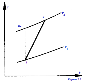
The fluid leaves therefore the stage in conditions B, at velocity CB. On the T,s diagram the transformation is usually represented as shown on Figure. 5.2, referring to conditions 1 and 2 at the stage inlet and outlet.
5.1.2 Definition of the major physical quantities in compression a. Actual head Heff The actual head Heff of a compressor stage (as for a whole machine) is the real work L1, 2 which is exchanged between fluid and environment per unit of weigth Following this assumption, the actual head Heff will be expressed by the relation
or by the relation
which, in case of machines where supposition is very close to actualities, assumes the well known form
Eor the adiabatic transformation (Qe = 0) The considerations resulting from a swift check of the above relations, are the following:
b. Polytropic head Hpol As previously stated, the polytropic head Hpol of . one stage, as well as of a whole machine, is defined to be the energy accumulated in the fluid always in the form of thermodynamic potential energy increase expressed by
The above relation for polytropic head Hpol is generally expressed in the form obtained by making the function bond explicit between pressure p and specific volume V of the gas, thus being generally given by the relation pvn = cost whereas n is the average exponent of the polytropic transformation between points 1 and 2 at the beginning and at the end of the real compression process (Figure. 5.2). If we replace above relation in the integral and develop it, we have the following relation
where Z1 is the compressibility factor calculated at the initial conditions; R is the gas characteristic constant; T1 is the gas suction temperature (OK) p1 is the gas Suction pressure; p2 is the gas discharge pressure; n is the polytropic transformation exponent assumed to be constant during the transformation. The units of measurement with which the polytropic head Hpol is expressed, are meters (kp m/kp) = (m), if the technical system for unit of measurement is adopted or, more properly, the units for the specific en
ergy (J/Kg) if the international system of units of measurement is applied. c. Polytropic efficienfry npol The polytropic efficiency npol of a compressor is defined to be the ratio between the polytropic head Hpol, just defined, and the actual head Heff expended to compress each kp of aeriform substance. Therefore according to what previously stated and considering the expressions already given for Hpol and Heff, we have
this relation can be in the form
for a perfect gas, whereas n is the average exponent of compression polytropic transformation between initial and final conditions k is the exponent of the relative isoentropic adiabatic transformation, at the same compression ratio and the real transformation considered Always referring to Figure. 5.2, remembering that perfect gas is considered,
hence is following, from which we can infer that is possible to estimate the polytropic efficiency, reliably and experimentally, by measuring the thermodynamic parameters at compressor suction (p1 and T1) anddischarge (p2 and T2) , provided that the handled gas could be assimilated to a perfect gas. Otherwise, Hpol and Heff values shall be calculated, after measuring pressure and temperature inlet and outlet values experimentally and being gas composition known, according to the equations of state which represent the gas behaviour as real as possible. The commonest equation of state applied to natural gas is the B.W.R.S. equation (Benedict; Webb, Rubbin, Starling).
d. Adiabatic head Had The adiabatic head in a compressor (Had) is the energy that would remain in the fluid because of a reversible, and hence isoenthropic, adiabatic compression_process (transformation 1 - 2is in Figure. 5.2) occurred between the same initial p1 and the final pg pressures, between which the real compres- sion process is performed. Head His is then obtained from the relation
considering k = cost. during the transformation, where k isvthe esponent binding pressures and specific volumes during isoentropic compression Z1 is the compressibility factor of the fluid at the beginning of reversible adiabatic transformation R is the gas characteristic constant T1 is the gas suction temperature p1 is the gas suction pressure p2 is the gas discharge pressure Also the quantity His, as for the polytropic head Hpol, is expressed in (m) or (J/kg) depending on the fact whether the technical system or the international system is applied as to the units of mea: surement. e. Adiabatic efficiency nad The adiabatic efficiency nad of a compressor is the ratio between adiabatic head Had, hereby defined, and the actual head Heff.
In spite of the considerations on polytropic efficiency, the adiabatic efficiency nad depends on the compression ratio pg/p1, besides on the machine and the nature of the fluid, as in case of perfect gas it is connected with the relation
This relation shows that the adiabatic efficiency nad is always lower than the polytropic efficiency npol (in an adiabatic compression process); the more the compression ratio "r" tends to 1 the more the adiabatic efficiency tends to the polytropic value. f. Power absorbed by the compressor The available diagrams, supplied by the manufacturer, which give head H (polytropic or adiabatic) and the efficiency (polytropic or adiabatic) for certain values of the speed of rotation n, allow to trace back to the real specific work L1, 2, (or actual head Heff) by means of the relations
where Pf represents the power lost owing to leakage and Pm the power lost owing to mechanical losses.
www.bennypass.it
|


+(39) 347 051 5328
Italy - Kazakhstan


09.00am to 18.00pm
About
We offer the best and economical solutions, backed by 27+ years of experience and international standards knowledge, echnological changes, and industrial systems.
Our Services
Marketing Materials


Marketing Materials1


