
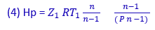
6.3 BASIC REGULATION THEORY It follows from the centrifugal compressor theory, by the law of similarities, that the surge points in a single stage compressor at the various speeds form a parabola with the apex at the origin and axis coinciding with the axis of ordinatescn1the polytropic head - volumetric capacity plane. In fact the following laws apply for the surge point at any speed: (1) Q1 = K' N (2) Hp = KN2 From equations (1) and (2), by substituting N, one gets the equation for the surge curve: (3) Hp = K" Q2 It is known that the polytropic head is obtained from the following formula:
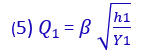
Should the suction capacity be measured with a calibrated orifice, we have:
where; h = orifice pressure loss in mmH2O
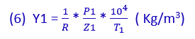
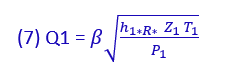
Substituting in equation (5) the Y1 value obtained from equation (6), one has:
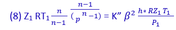
where h1 is in Kg/cm2 Again substituting the n. (4) and (7) formules in equation (3):
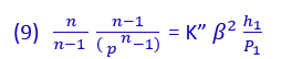
Simplifying:
or:
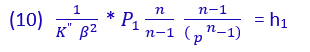
To avoid surging in any suction or speed conditions of the machine, it can be noted from this formula that it is sufficient to see that:
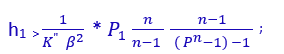
or:
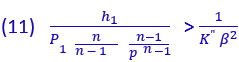
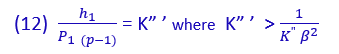
Formula (11) is important for the following reasons:
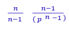
In short, formula (11) employs the compression ratio sensitive to the suction and speed conditions to compensate the capacity. Although considerably simplified formula (11) is still too complex to be realized with very simple instruments. If the compression ratio is small enough, as in the case of single-stage and two-stage compressors, it is possible to substitute the quantity
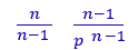
with the quantity p - 1 without making any great error. However, any error is to the advantage of greater safet being
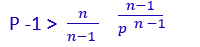
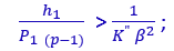
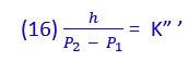
Therefore formula (11) becomes
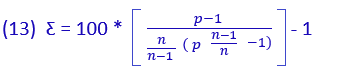
let us make
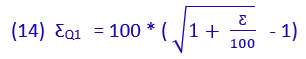
The percentage error which is made is obtained from the following expression:
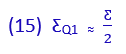
Expression n. (13) involves a percentage error in the suction capacity
In general one can say that the error in capacity si approximately half of that made substituting p - 1 with
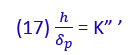
Formula (12) can also be written as:
or:
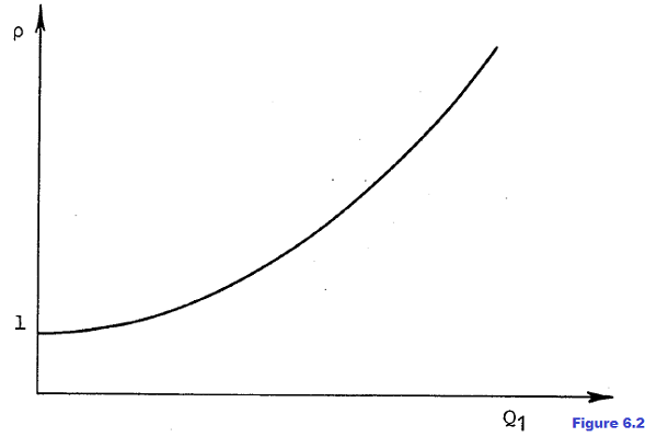
This is the equation of a parabola (in the plane p,Q1) with the origin at the point with coordinates p = 1; Q1 = 0 (see figure. 6.2)
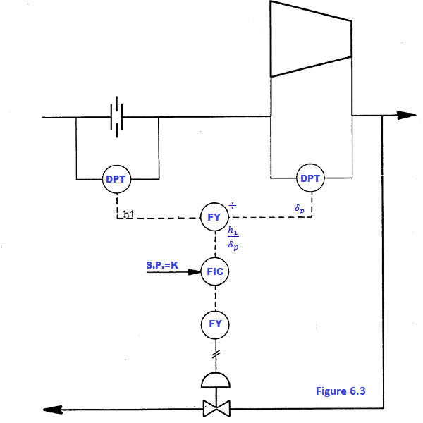
It demonstrates the extreme simplicity of this type of antisurge system which collects all the information necessary to protect the machine from the process with only two instruments (two differential transmitters) . The two signals are sent to a divider which works out the ratio. This ratio is sent to a regulator, on which the K" ' value, i.e. the antisurge regulation set-point, is set. The regulator, acting on the by-pass valve, keeps the ratio "from going below the established set-point, thus fulfilling the requirements. Hereafter (see figure. 6.3) a typical diagram
www.bennypass.it
|


+(39) 347 051 5328
Italy - Kazakhstan


09.00am to 18.00pm
About
We offer the best and economical solutions, backed by 27+ years of experience and international standards knowledge, echnological changes, and industrial systems.
Our Services
Marketing Materials


Marketing Materials1


