
7. LUBE AND SEAL OIL SYSTEMS Every centrifugal compressor has a lube oil sys tem: seal oil systems, however, are not always essential, such as when labyrinth seals are used, and a certain gas leakage is admitted as in air compressors. Another case where they are not necessary is where seals are formed by injecting or extracting compressed gas (e.g. CO2 compressors). Inert gas should be used‘ for injection when the oil and process gas must not come into contact (oxygen compressors). 7.1 LUBE OIL SYSTEM Lube oil is used to create lift by forming a film of oil between the shaft and bearing, and to cool the bearing to keep it at an optimum temperature as power is dissipated in the bedring, causing it to heat up. Lubrication and sealing system oil should be cooled in order to maintain good viscosity; a cooling system is therefore provided. Oil viscosity is a very important parameter which along with the geometrical characteristics of the bearings considerably influences rotor dynamic behavior and consequently vibrations: a lubricant may have sufficient damping power to allow operation at near critical speeds. Low viscosity due to high bearing temperatures would make operation unsafe: if the weight of the rotor is not supported by sufficient lift the oil film could break and make the shaft and bearing suffaces work in contact thus increasing temperatures and the risk of the bearing white metal burning.
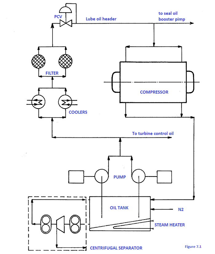
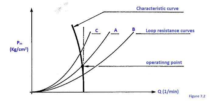
It should be stressed that the oil flow has to be sufficient to dispose of the heat generated by the bearings. Hence the need for the bearing temperature to always be kept under control: it is regulated by varying the inlet oil pressure with the pressure control valve (PCV). Also the drained oil temperature should be kept under control to check the heat exchange between the bearing and oil is correct. A schematic diagram of a lube oil system is shown n figure. 7.1. The following are the main components: 1.1 Tank The tank is always fitted with an electric or steam heater to give the oil the right viscosity for start-up. It has a sufficient capacity to ensure both a good retention time (feeding the oil pumps even without oil returning to the tank through it being lost in the system) and a certain time in a receiver to prevent it from foaming. In some cases gas could get into the tank which could form explosive mixtures in contact with oil vapours; a light flow of inert gas (N2) is applied to the oil surface to prevent this. Centrifugal compressors driven by steam turbines have a (Centrifugal) separator which takes oil from the bottom of the tank and centrifuges it to separate the water formed by steam leakages from the prime mover turbine condensing and being recycled into the tank. The separator is normally sized to handle all the tank oil in a single day. It may be design ed also to separate sludge and dirt; these are called clarifying centrifuges. 7.1.2 Pumgs The oil is drawn from the tank and sent into the system by a series of pumps. Either positive displacement or centrifugal pumps may be used; let's briefly look at the difference between these two types of pumps. A positive displacement pump gives more or less the same oil flow at varying pressures depending on the system's resistance to pressure. Its characteristic curve is therefore as shown in figure. 7.2. The operating point is where the characteristic curve and system's resistance curve (A in this case) cross.
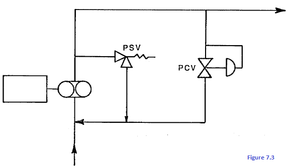
Theoretically, a positive displacement pump‘s characteristic curve is parallel to the Y axis but in practice flow gradually decreases on a rise in pressure because internal leakages (fluid leaks towards suction) increase with pressure. The only way to change the operating point is to alter the system's resistance curve since these pumps are generally set speed. It may be easily altered by adding a by-pass valve to direct part of the oil back to the tank. By varying the opening of the valve it is possible to move the operating point along the characteristic curve; for example, curve A representes the system's resistance with the by-pass valve part open and curve C the system's resistance with the by-pass more closed and B with it wider open. This valve normally open automatically operated by the oil pressure that is to be kept constant (see figure. 7.3).
There are always two pumps: one main pump and an auxiliary pump; the latter is normally operated by an electric motor with a preferential feeder line. Downstream from the pumps (see figure. 7.1) the piping branches: the turbine control oil system (for compressors with steam turbine drivers) starts on one line and on the other there are the coolers, filters, lube and seal oil systems (naturally unless there is no seal oil system or it is independent) Turbine control oil is not cooled as it does not require a high viscosity. It is approximately 8 atm.
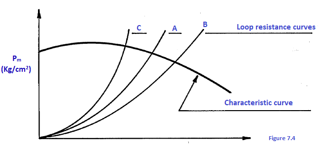
7.1.3 Coolers As already mentioned, oil has to be cooled in order to maintain good viscosity. A cooling system is therefore provided consisting of two water or air exchangers in parallel which are made to operate alternately by three-way valves The oil temperature is controlled regulating the coolant flow. 7.1.4 Filters Clean oil should be kept circulating for optimum lubrication Of bearings and seals and to prevent wear; there are therefore two filters working alternately in parallel. The filters are Critical system components which have to be kept under control with a differenLial pressure gauge. In short, a by-pass is necessary to regulate a positive displacement pump's delivery pressure; in addition, a relief valve is always required to prevent uncontrolled pressure rises caused by accidental increases in system resistance. A centrifugal pump, however, has a delivery pressure which varies little on changing the flow established by the system's resistance. The characteristic curve is as shown in figure 7.4
To obtain a given delivery pressure it is therefore necessary to select the pump accordingly. In this case neither a relief nor a by-pass valve are required; the delivery pressure is regulated varying the speed. It is therefore understood that centrifugal pumps would be the most appropriate but centrifugal pumps have lower efficiencies than positive displacement pumps for low flows. When there is too muche pressure loss due to dirty filters they should be changed or they might break otherwise. When there are double filters and double coolers it is necessary that flow change over smoothly the three-way valves so half way causing the pressure to rise upstream (and therefore the relief valves to open) and a temporary interruption in flow (resulting in a minimum pressure trip). 7.1. 5 Control valve (PCV) After the filters there is a self-actuated pressure control valve (PCV) which keeps the oil pressure to the bearings constant between 1.5 and 2.5 kg/cm2. Every oil line to the bearings is fitted with an adjustable orifice and a pressure tap for regulating the pressure to the individual bearings The oil should be able to easily drain without foaming or evaporating which would make lubrication difficult. It is therefore drained by qravity to the tank through adequately sized sloping piping; the inlet is far from the pump suction. Vents are installed to prevent overpressure which could prevent regular oil defluxion.
7.1.6 Instrumentation on the lube oil system The instrumentation normally installed on a lube oil system comprises the following:
www.bennypass.it
|

+(39) 347 051 5328
Italy - Kazakhstan


09.00am to 18.00pm
About
We offer the best and economical solutions, backed by 27+ years of experience and international standards knowledge, echnological changes, and industrial systems.
Our Services
Marketing Materials


Marketing Materials1


