
7.2 SEAL OIL SYSTEM The oil system used as a compressor gas seal may either branch from a lubrication system oil header or be independent with its own oil tank, which may be different from the one used for lubrication. To illustrate the sealing system and its components better let's first see how the gas is buffered at the compressor shaft ends.
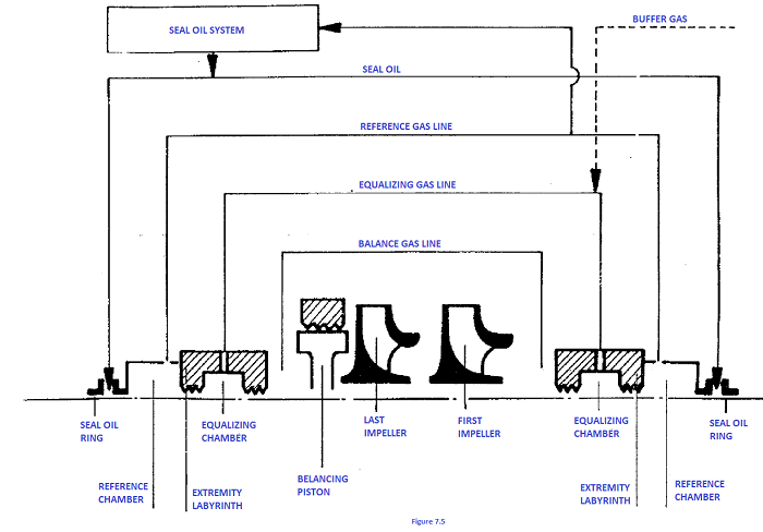
Having the end impeller delivery pressure on one side of the drum, the compressor inlet pressure is applied to the other by an external connection (balancing line, see figure. 7.5) In this way gas pressures at both ends of the
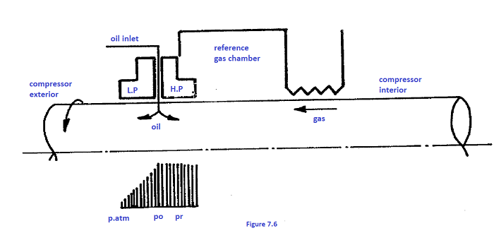
rotor are roughly balanced. To get even closer pressure levels and, therefore, the same operating conditions for the shaft-end oil seals, another external connection is made between tho balancing chambers (balancing line, see figure.7.5). Reference gas chambers are positioned outside the shaft-end labyrinths. They are connected to achieve the same pressure as that used as reference for the Oil seal system (see figure.7-5 for a block diagram In special cases, when the seal oil and process gas have to be kept separate, inert gas is injected into the balancing chamber (buffer gas system) at a pressure that allows it to leak both inwards and outwards forming a seal. The system adopteél in 90% of the cases is an oil film between the floating rings and shaft with very tight clearances (a few hundredths of a millimetre) for the high pressure ring and approximately 0.15 mm. for ‘the low pressure ring (see figure. 7.6). The oil is injected between the two rings (HP and LP) at a pressure maintained constantly above the gas pressure by approximately 0.5 kg/cmz so that thore is no gas leakage towards the exterior and only a small quantity of oil passes through the H.P. ring and comes into contact with the gas (few tens of litres per day). The oil mixed in the gas reaches the traps where it is separated from the gas; after an additional separation it is returned to the main tank. The heat generated by friction in the HP ring gap is not disposed of by the oil flow through it which is low on account of the small clearance between the HP ring and shaft and the low oil/gas differential pressure. To avoid damaging (burning) the bearing white metal, the LP ring clearance plus the high difference in pressure towards the exterior are such as to cause a good oil flow and therefore good heat absorption. This oil, not being in contact with the gas, is drained straight into the tank through the lube oil return line (in combined systems). To maintain a constant differential pressure of approx 0.4 to 0.5 kg/cm2 between the oil and gas two types of system are normally used to suit different compressor plant requirements and operating conditions. The first system consists in maintaining the overhead tank level constant about seven metres above the compressor axis so that the seal oil pressure (Po) is the same as the gas pressure (Pr) plus the head (H) (see figure. 7.7). The second system is essentially based on automatic control of a differential oil/gas valve, which maintains the desired differential pressure of approx. 0.5 Ate keeping the overhead tank completely full and under pressure (see figure. 7.8) In this case the tank position does not affect operation Of the system so that it may be installed directly on the compressor thus eliminating all the problems related with an overhead tank.
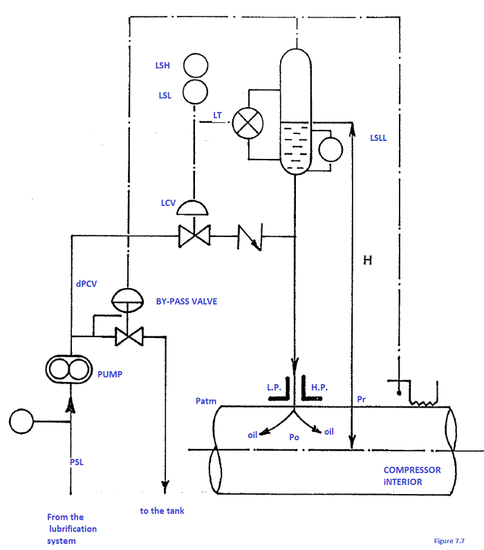
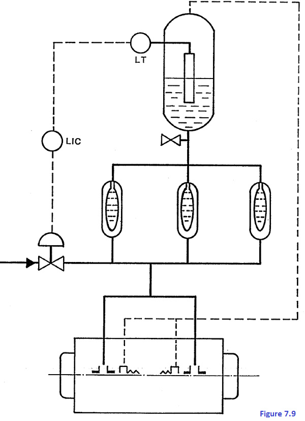
7.2.1 First system (see figure- 7.7) The positive-displacemcnt pump pumps the oil at approx. 10 At; higher than the reference gas pressure established by the differential pressure control valve (DPCV) so that the level control valve (LCV) can maintain a constant tank level under the control of the level transmitter.
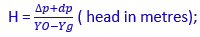
On any increase in oil flow through the seal rings the level valve shall open wider and the vent valve close correspondingly. Let's see the relations between pressures at the various points of this system. First of all, if we want the head in metres of oil to give the differential pressure required at the sides of the high pressure ring, we have to connect the overhead tank and pressure chamber. Thus: Po = Pg + YOH - dp; where Po = seal ring inlet oil pressure Pg = overhead tank level gas pressure in turn expressed as: Pg = Pr - YgH (Yg = gas specific gravity) Yo = oil specific gravity dp = losses in the tank-seal line to be considered if the oil flow is great compared with the diameter. It is disregarded for flows of 30 to 40 1/min. and 2 to 3 inch diameters. From the above one obtains: Po = Pr - YgH + YOH - dp = Pr+ H (YO - dp) (Po - Pr) = Δp = ( YO - Yg) H - dp; Δp + dp = H (YO - Yg) and hence:
disregarding dp and Yg, H = While dp need not be considered when sufficient diameter pipes are used the same may not be said for yg which may even reach around 0.5 y O for high pressure heavy gas; in this case double the the head would be required to obtain the same differential pressure. For example, with oil specific gravity equal to 0.8 kg/dm3 roughly a 5 meter head is needed to achieve a differential pressure of approximately 0.4 kg/cm2.
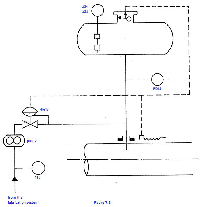
7.2.2 Second system (see fig. 7.8)
As previously mentioned, the oil pressure is maintained at approximately 0.7 to 1 kg/cm2 higher than the gas by valve DPCV for any gas pressure. The tank always works under pressure; its volume depends on the retention time one wishes to have on compressor shutdown due to the minimum oil/gas differential pressure.
7.2.3 lnstrumentation on the seal oil system The instruments normally installed to be able to depend on gas buffering in compressors are:
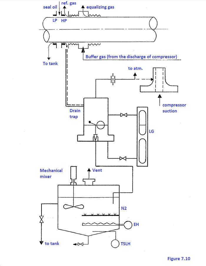
The oil that has sealed the gas passes into the reference gas chamber and is drained by gravity to the traps where it is separated (see figure. 7.10). A float valve sends the oil to the gas separating tank where it is kept at a temperature of approx. 85 to 900C. A mechanical mixer or an inert gas (nitrogen) scrubber may be used if necessary for complete stripping of any gas left in the oil. The oil is then analysed and may be returned to the main tank or further regenerated. The gas comes out the top of the trap and is released through a calibrated orifice a few millimeters wide thus creating a downward flow inside the compressor towards the trap entraining the seal oil. Since the reference gas pressure is practically the same as the compressor suction pressure it will have to be increased if the gas is to be returned from the traps to the compressor suction with a buffer gas line on the balance line in order to always have a positive differential pressure on the orifice or by taking the reference gas from an intermediate compressor stage. Seal oil drainage systems normally have the following instrumentation:
www.bennypass.it |


+(39) 347 051 5328
Italy - Kazakhstan


09.00am to 18.00pm
About
We offer the best and economical solutions, backed by 27+ years of experience and international standards knowledge, echnological changes, and industrial systems.
Our Services
Marketing Materials


Marketing Materials1


