
8 .2 SYNCHRONOUS VIBRATIONS Synchronous vibrations are usually attributable to one or a combination of the two following causes:
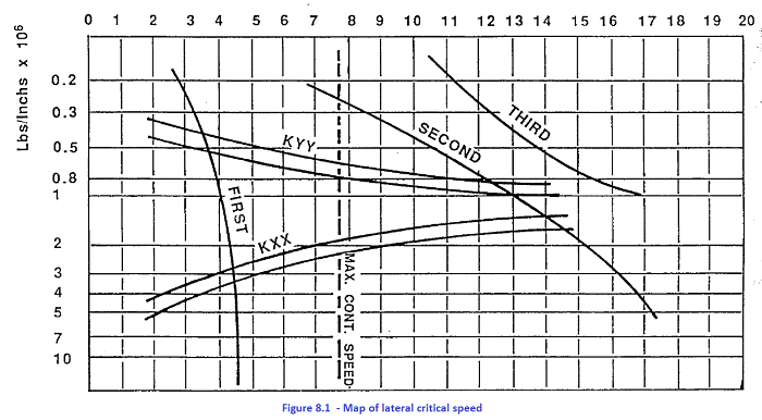
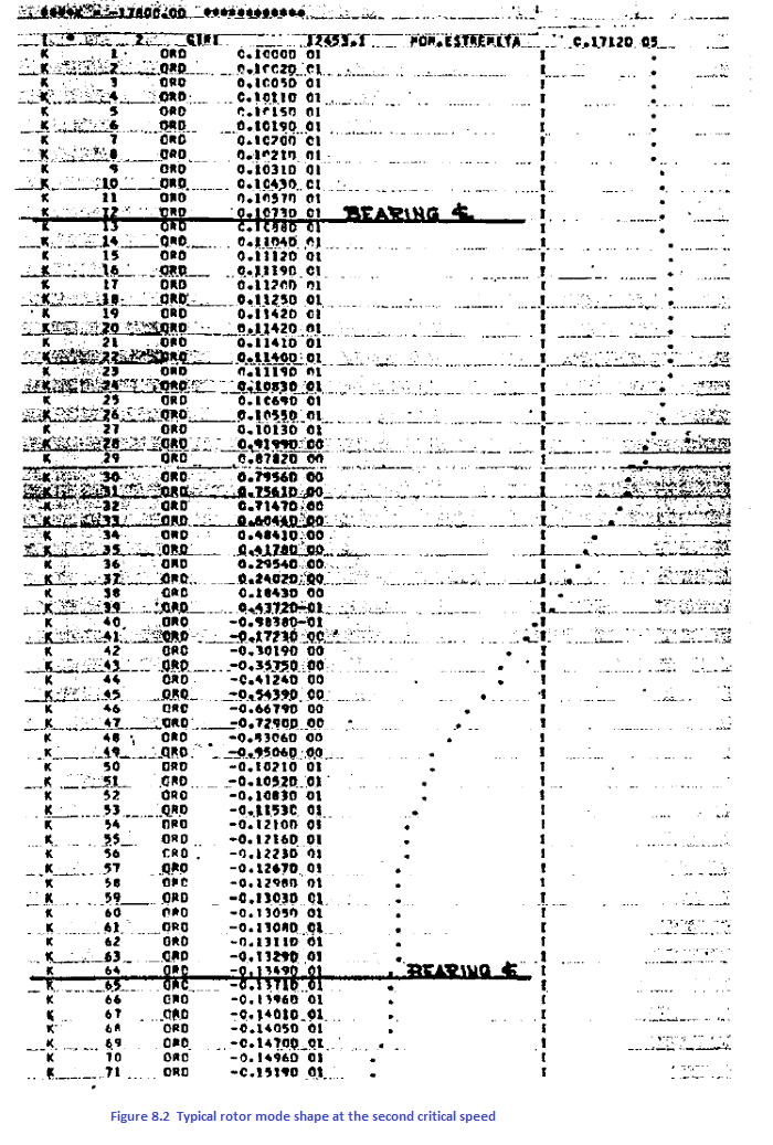
As regards point a), machine manufacturers 110w have equipment which permits achievement of avery accurate balancing (see note). This considerable accuracy in balancing is however sometimes upset by accidental causes so that point b) assumes great importance; correct design of the rotor-bearing system must assure acceptable vibration levels even when accidental causes destroy the original state of perfect balance. Two approaches are usually used to predict the synchronous dynamic behaviour of a rotor. The first approach is the Myhlestad-Prhol numerical calculation that considers the rotor as a dynamic system consisting of a number of concentrated masses attached to a massless shaft supported by bearings. The computer programme solves the system for a variety of constant support values over the entire possible range. A diagram can be made in which the lateral critical speeds are a function of the equivalent stiffness of the supports. The actual values of lateral critical speedscan be established on the basis of the knowledge one has of the bearing stiffness (figure. 8.1). The original speed programme also calculates the rotor mode shapes at the critical speeds for each specified value of the bearing stiffness (fig.3-2)-The mode shapes are important because they indicate the relative
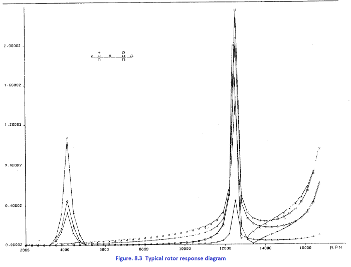
vibration amplitude at each station along the rotor. If relative amplitudes at the bearings are low a high unbal ance producing considerable deflection in some sections of the shaft will cause very small relative motion in the bearings. Without relative motion, damping of the bearings cannot be effective. Thus the bearings are not placed in the most efficacious position, and their position must be corrected. The second approach is to carry out the shaft response calculation in which the rotor motion throughout its operating speed range is studied as a damped system response to an unbalancing excitation. The unbalancesare generally placed where they may be expected to occur, i.e. at impellers, couplings,etc. The amplitude The amplitude of rotor motion is calulated at selected station along the rotor. Coefficients (8) simulating the dynamic stiffness and damping of the bearing are included in the calculation. The calculated whirl orbits are generally elliptical due to the difference between the vertical and horizontal stiffness and damping. A response diagram represents the variation with speed of the semi—major axis of the elliptical whirl orbit at selected stations along the rotor (figure. 8.3). Various tests carried out directly in actual operating conditions have shown that the frequencies and amplitudes measured are close to the expected values. The design parameters available to act upon damping capacities and resonance values are: bearing positions, especially with_respect to the shaft overhangs, bearing type, type of lubricating fluid, coupling type and obviously elastic characteristics of the rotor.
www.bennypass.it |

+(39) 347 051 5328
Italy - Kazakhstan


09.00am to 18.00pm
About
We offer the best and economical solutions, backed by 27+ years of experience and international standards knowledge, echnological changes, and industrial systems.
Our Services
Marketing Materials


Marketing Materials1


