
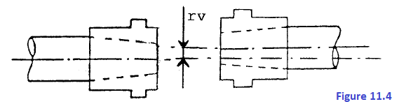
11.2 ALIGNMENT By alignment we mean the coincidence of the axis of one machine with the extension of the axis of the other during normal operation. To accomplish this, you must remember that all compressors undergo a certain vertical displacement due to the expansion of the support feet, due to the difference in temperature between the machine running and the machine at rest. The procedure to follow for ‘finding the relative position between two shafts to be aligned radially (see figure. 11.4) is to measure with special instruments (centeisimal dial indicators)
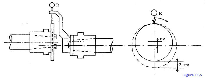
the difference between the position of four points on the read circumference (disk on drive machine) along the axes perpendicular to the corresponding points on the circumference generated by the indicator, made to rotate around the axis of the driven machine, taken as a reference (see figure. 11.5).
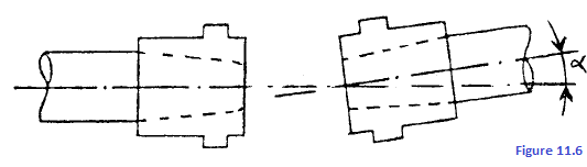
In addition, to find the amount of relative angular deviation between the two shafts (see figure. 11.6), use
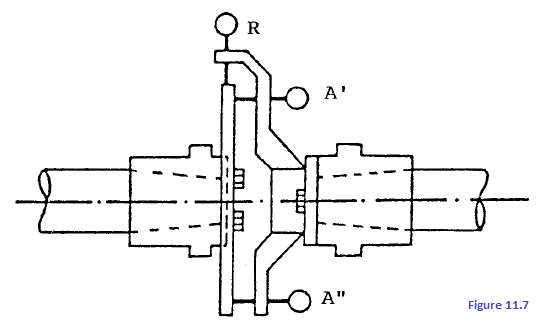
dial indicators installed on one of the two shafts and in contact with the surface of a disk mounted perpendicularly on the other shaft (see figure. 11.7).
As previously stated, the reading is taken at four points on the disk in correspondence with the perpendicular axes. This reading shows in linear form the angular deviation between the two shafts. To avoid errors due to eccentricity and machining imperferctions in the disk, you must rotate both shafts 90° for each reading so that the dial indicator is always read in the same point in which it was set to zero. This procedure, however, may lead to errors due to probable axial movements; to eliminate them, use two comparators mounted axially at 180°. Then considering the difference in their readings, you may obtain an error-free value.
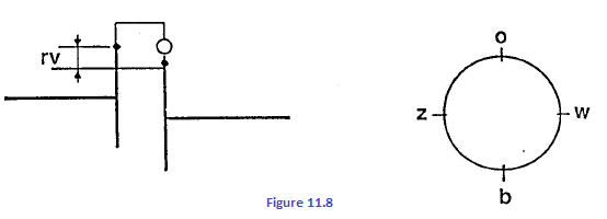
11.2.1 Alignment and coupling procedures Start alignment, taking the drive equipment as a reference. Measuring radial alignment Zero the radial dial with reference to vertical, as shown in figure 11.8
Rotate both shafts in the direction expected for operation, taking gauge readings at 90° intervals. Indicator reads minus when the plunger moves outward and plus when the plunger moves inward. Take readings observing the coupling hubs in the same axial direction toward the driven machines. Make sure that the indicators start out at midrange and rest squarely on the shaft.
where "b" is the reading of the dial indicator following a 180° rotation. Apart from slight errors, the algebraic sum of the post-90° (w) and post-270° (z) readings coincides with the post-l80° reading:
whereas their algebraic semi-difference indicates horizontal radial misalignment:
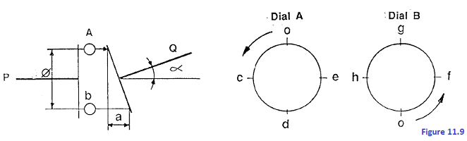
NOTE: It is imperative to take into account the plus and minus signs of "w" and "z". Measuring axial alignment Axial alignment, i.e. angular alignment of the shafts, is measured by means of two dial indicators set at zero when they are positioned at 12 and 6 o'clock. Rotate bozh shafts and record measurements at each 90 interval, as shown in figure. 11.9.
Assuming that both indicators are attached onto the flange of shaft P, the indicator button will track on the flange of shaft Q. Readings are recorded viewing from shaft P. Results are:
The + or - Signs of "c", "e", "f" and "h" must be taken into consideration.
Cold alignment After the alignment has been measured, position each machine in the group in such a way that thermal exparsion or contraction will bring the shafts into proper alignment during normal operations. The alignment charts for each of the couplings provided on the following pages give shaft positions and operating speed, predicted expansion and thus the positicns required for cold shafts. In addition, they show the values to be read off the indicators to obtain the required shaft position. The shaft displacement values were calculated assuming amziert temperature and an average support temperature as indicated in the charts. If temperatures differ greatly from those indicated, the operator must calculate the actual displacement values. Esample: the new displacement value of a L support is expressed in terms of the old L value multiplied by the ratio
where:
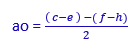
Since these values are not perfectly accurate, however, it is suggested that a check be performed while the machine is at normal operating speed. For correct positioning of the machines, first correct the axial alignment on the vertical plane by adjusting the height of the shims placed under the bearing plate of the compressor. In the case of figure. 11.10, the shim correction under the outer support of the shaft is expressed by the formula
If the correction to be made is rather significant (several tenths of a mm, for example), it is best to adjust the shims between the grouted plates and the base-plate
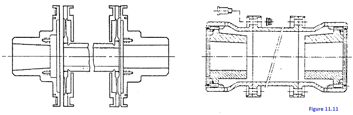
To correct radial alignment "rv", the compressor must be either raised or lowered (without changihg its angular position) by inserting or removing a shim beneath each support plate of height "rv". To correct axial and radial misalignment on the horizontal plane, just move the compressor horizontally by means of the adjustment screws in its feet. To determine the amount of displacement, follow the same rules as for vertical misalignment correction. Piping Connection and Doweling After alignment has been completed, you may begin connecting the piping. The dial indicators must be installed in at convenient points on the foundation or on a structure not attached to the machine. The indicator buttons must be placed in contact with the machine to detect any piping displacement which could cause coupling misalignment. After an initial period of operation at normal speed re-check alignment and dowel the machines. Reference dowels are located on the plates where the keys keep the machines aligned longitudinally and transversely, even if there is strong thrust caused by the gas piping and deformation due to thermal expansion. The keys placed between the compressor feet and support plates position the machines longitudinally, while the keys placed along the vertical axis of the compressor position the machines transversely. Cougling The machines composing the compressor group are coupled together with toothed or diaghram couplings (see figure. 11.11), which may be secured to the shafts by means of
one or two keys or, more commonly, forced cold onto the conical end of the shaft with a hydraulic device supplied with the machine or by heating the coupling halves in electric furnaces. Make sure when positioning the machines that the dis- tance between the coupling halves is that indicated and that the spacer has the play required in the drawings.
www.bennypass.it
|


+(39) 347 051 5328
Italy - Kazakhstan


09.00am to 18.00pm
About
We offer the best and economical solutions, backed by 27+ years of experience and international standards knowledge, echnological changes, and industrial systems.
Our Services
Marketing Materials


Marketing Materials1


