
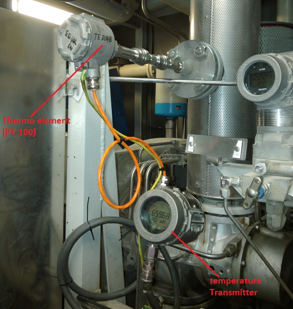
The temperature Transmitter (Working Principle)
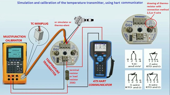
A temperature transmitters converts the thermocouple or RTD signal to a 4-20 mA output signal and is the ideal solution for many remote temperature measurement applications. 4-20ma transmitters have definite advantages over conventional temperature measuring devices, but must be selected with caution in order to avoid “ground loop” problems. In many cases, the temperature of a remote process must be monitored. Common temperature sensing devices such as thermocouples and RTD’s produce very small “signals.” These sensors can be connected to a two-wire transmitter that will amplify and condition the small signal. Once conditioned to a usable level, this signal can be transmitted through ordinary copper wire and used to drive other equipment such as meters, dataloggers, chart recorders, computers or controllers. A temperature transmitter draws current from a remote dc power supply in proportion to its sensor input. The actual signal is transmitted as a change in the power supply current (4 - 20mA) Specifically, a thermo-resistor (PT100) input transmitter will draw 4 mA of current from a dc power supply when measuring the lowest temperature of the process. Then, as the temperature rises, the thermocouple transmitter will draw proportionally more current, until it reaches 20 mA. This 20 mA signal corresponds to the thermo-resistor highest sensed temperature. The transmitter’s internal signal-conditioning circuitry (powered by a portion of the 4-20 mA current) determines the temperature range that the output current signal will represent. The type of connection always depends on which type of thermo-resistor available. the thermal-resistor available are 2 wire, or 3 wire, or 4 wire, for more details visit the thermo-resistor page here. Even if the type of resistance thermometer changes, the transmitter remain exactly the same, but internal setup of transmitter should be selected the type of thermo-resistor if is 2,3,4 wire. below the Figure with a typical temperature transmitter connection.
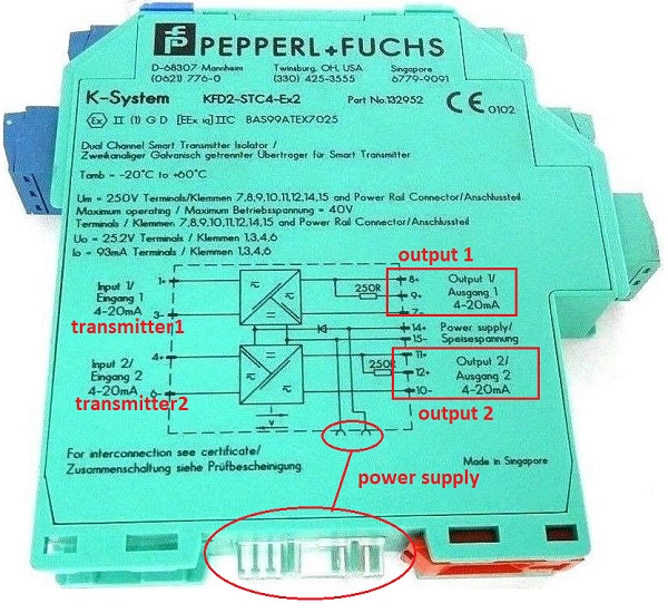
Note: the load resistor in normal connection should be under the barrier or analog input (AI) The figure below is an example of connection with barrier Pepperl + Fuchs KFD2-STC4-Ex2 (two chanel)
Current Loop Basics The 4 to 20mA current loop is a very robust sensor signaling standard. Current loops are ideal for data transmission. All the signaling current flows through all components; the same current flows even if the wire terminations are less than perfect. All the components in the loop drop voltage due to the signaling current flowing through them. The signaling current is not affected as long as the power supply voltage is greater than the sum of the voltage drops around the loop at the maximum signaling current of 20mA. Figure below shows a schematic of the simplest 4 to 20mA current loop (There are four components only).
Current supplied from the power supply flows through the wire to the transmitter. The transmitter regulates the current flow. The transmitter only allows a current proportional to the measured parameter to flow, called the loop current. The current flows back to the controller through the wire. The loop current flows through Rreceiver to ground and returns to the power supply. The current flowing through Rreceiver produces a voltage that is easily measured by an analog input. For a 250Ω resistor, the voltage will be 1 VDC at 4 mA and 5VDC at 20mA. For more details click here
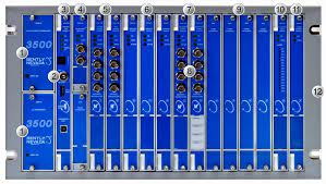
Note: Devices on a current loop are either active or passive. “Active” in this context means that a device has a voltage source that powers the loop. There can only be one active device on a current loop. “Passive” devices are the exact opposite – they do not have their own voltage source and therefore are dependent on an external source. You can find more information about active/passive signals here. The figure above show a classic connection loop, but in some cases the connection can change, all depende which AI is available. The Figure below show a different connection with Bently Nevada 3500 series.
This type of connection does not need any exsternal transmitter. The electronic card of Bendly Nevada directly reads the value in Ω from the thermo-element and convert the signal. The signal can be transmitted in analog mode (4 - 20mA) on in serial mode (modbus) depende which configuration is set in the electronic card. Also the Bendly Nevada can be set in digital mode, means give to electronic card a setting with value of H or HH or LL temperature (high/low temperature), then when the temperature will reaches the set point the electronic card itself de-energize a micro relay inside which will open a contact that pilot the PLC (UCP) with tripping the machine instantly. All the machines with high risk using rigorously the digital contact as explained above. A millisecond delay could be fatal, this is the reason. |


+(39) 347 051 5328
Italy - Kazakhstan


09.00am to 18.00pm
About
We offer the best and economical solutions, backed by 27+ years of experience and international standards knowledge, echnological changes, and industrial systems.
Our Services
Marketing Materials


Marketing Materials1


