
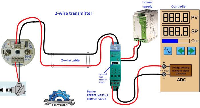
Active & passive output and two-wire & four-wire transmitters Introduction If a device has a passive output, then you need an external power supply to support it. If the device is active, then you already have an output signal with the power supply, so you don’t need another one. Passive Loop Two-wire transmitters are passive because they need external power to close the loop before you can read the signal (see photo below).
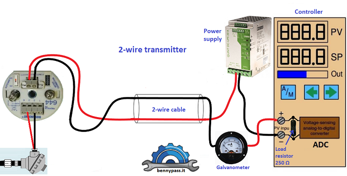
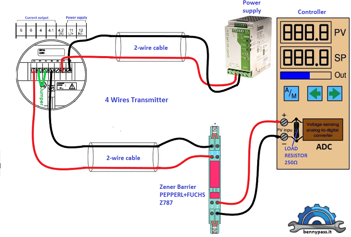
The Figure below show a connection without barrier and with load resistor on board of electronic card.
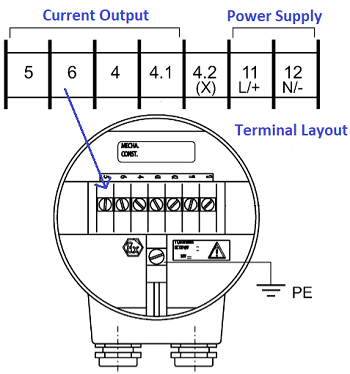
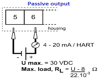
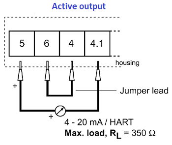
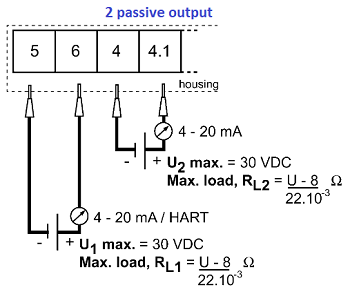
Some transmitters are with 4 wires, means 2 wires for the power supply and 2 wires for the signal 4-20mA. they also can be configured as passive or active. In this example let's take as a reference KROHNE BM 100 transmitter which is with triple configuration. Below the figures with all type connections.
As you can see from Figures above this level transmitter can be configurate active or passive circuit. With jumper on terminal 6 - 4 connected the circuit will be active, while, without jumper the circuit will be passive. Note: Sometimes it happens to find transmitters with 4-wires, means 2 wires for power and 2 wires for signal which can be passive or active. Be careful because even with 4 wires some transmitter can be configured only passive and not active or vice versa (read the manual of transmitter)
Active Loop The Figure below show the typical connection of an active loop
As you can see from Figure above the circuit remain almost same with passive loop but power supply disappeared from barrier and electronic card. Normally this type of connection on new plants it is no longer used, or rather it is used where a power supply is mandatory like an electrical actuator or radar instrumentation, etc. In any case these equipment’s will however be configured as passive for following the standard with others field configuration. Normally when an instrument is active there should be also the possibility of being able to change to passive. Note: Active and passive devices provide different outputs. But some transmitters also come with features that allow you to select whether the device provides an active or passive output ( as the level transmitter KROHNE BM 100). Basic Concepts First, need to understand the following basic concepts: current source (the output of a 4-wire transmitter is usually a current source signal), 3-wire transmitter, and 2-wire transmitter
Digital conversion Like all electronic equipment, in order to read an analog signal, a microcontroller must convert it to digital and then process it. The temperature, level, pressure transmitters which sending an analog signal to the AI cards, the AI cards (microcontroller) must be converting the signal in digital as per binary system (The CPU working with 0 - 1 as you know). The microcontroller (PLC) can be an 8,10,16,32,64 bits, more bits available and more the measurement will be accurate. The video below shows how the PLC converting the analog signal in digital signal. has been used the simulator proteus and a micro-controller PIC24FJ128JA010. the conversion has been performed with 10bits (1023 Dec) of configuration and analog voltage 0-5Volts.
The AI card read the voltage, means 1 volt matches with 4mA and 5 volt matches to 20mA. As an example, you can see the figure above with Galvanometer drawing, if there was a multimeter selected in volts and connected in parallel to Galvanometer or the AI card you can see that, when the Galvanometer will indicate 4mA the multimeter read 1volt, if the Galvanometer will indicate 12mA the multimeter read 2.5Volts, or 20mA the multimeter will read 5 Volts. Conclusion
Method of judging whether external power supply is needed in the signal acquisition loop: Disconnect the signal acquisition loop, and connect a voltmeter to the two lines of the field device (transmitter). If there is voltage, it means the field device outputs active signals. If there is no voltage, it means the field device outputs passive signals.
If you have any more questions, give us a call, and our engineers will help.
www.bennypass.it |

+(39) 347 051 5328
Italy - Kazakhstan


09.00am to 18.00pm
About
We offer the best and economical solutions, backed by 27+ years of experience and international standards knowledge, echnological changes, and industrial systems.
Our Services
Marketing Materials


Marketing Materials1


