
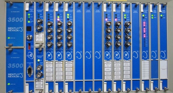
Bently Nevada- Asset Condition Monitoring 3500 system Indroduction The Bently Nevada product line has been synonymous with machinery protection and condition monitoring for more than 50 years. From refineries and petrochemical plants to hydroelectric facilities and wind farms, Bently Nevada Asset Condition Monitoring offers trusted and proven vibration monitoring equipment and a comprehensive services portfolio to help improve the reliability and performance of production assets like turbines, compressors, motors, generators, and everything in between. Description The 3500 System provides continuous, online monitoring suitable for machinery protection applications, and is designed to meet the requirements of the American Petroleum Institute’s API 670 standard for such systems. The system’s modular rack-based design includes the following components:
let's try to describe them all: Instrument Rack
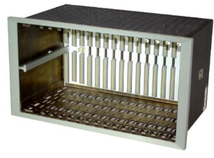
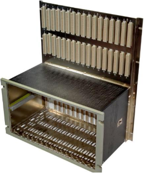
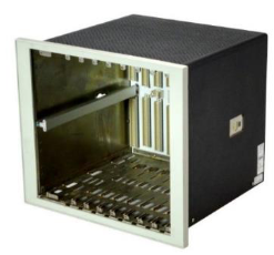
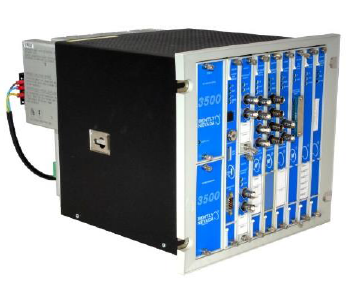
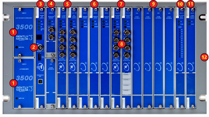
The rack provides slots for two Power Supplies and a TDIin the left-most rack positions that are reserved exclusively for these modules. The remaining 14 slots in the rack can accommodate any combination of monitor, display, relay, Keyphasor module, and communication gateway modules. All modules plug into the rack’s backplane and consist of a main module and an associated I/O module. The I/O module installs at the rear of the rack for panel-mount systems, and above the main module for bulkhead-mount systems. Standard rack depth is 349 mm (13.75 inches), while bulkhead mount rack depth is 267 mm (10.5 inches).NEMA 4 and 4X weatherproof housings are available when required for environmental protection or when purge airis used. Mini Rack
A minirack (12” wide instead of 19”) is also available and features 7 available monitor slots instead of 14. Like its larger counterpart, the left-most slots are reserved for the Power Supply or Supplies and TDI Module. The minirack may be mounted in a panel cutout or, using an optional adapter plate, on 19” EIA mounting rails. Bulkhead mounting is not available Power Supply
The 3500/15 Power Supply can be ordered for ac or dc input power, providing compatibility with voltage sources worldwide. Line noise filters are standard. The 3500 Rack can operate from a single supply, or dual supplies can be used to provide redundancy for situations thatcannot tolerate power interruption Dual supplies reside in the upper and lower positions of the left-most rack slot. Redundant supplies can useseparate voltage sources. For example, the primary (lower) supply can operate with 120 Vac power while the backup (upper) supply can be powered from an uninterruptible 24 Vdc source. Each supply can individually provide power to the entire rack and its modules. When redundant supplies are used, the lowersupply acts as primary power for the rack while the uppersupply acts as a backup, ready to instantly and automatically operate as the primary rack supply without interrupting rack functions should the primary supply fail. The 3500/15 Power Supply module has self-monitoring functions that allow it to determine if all its output voltages are within specifications. The module annunciates this via a green Supply OK LED on the power supply’s front panel.
3500/22M Transient Data Interface (TDI)
The TDI is the 3500 Rack’s primary interface to the configuration, display, and condition monitoring software. Each rack requires one TDI, locatedin the rack slot immediately adjacent to the power supply slot. The TDI supportsa proprietary protocol used by the 3500 Configuration Software to configure the rack and the 3500 Operator Display Software to retrieve rack data and statuses. The TDI also provides a direct interface with System 1*Condition Monitoring and Diagnostic software without the need for an external communications processor. The RackOK relay is located within the TDI’s I/O module. It is driven by NOT OKconditions within the TDI itself and within other modules in the rack. Note: Dozens of possible eventswithin the rack can drive the Rack OK relayto NOT OKcondition. For this reason, the Rack OK relay it is not intended for use as part of a machinery auto-shutdown circuit. Itshould be used for general annunciation purposes only. The TDI supportsself-monitoringfunctions both for itselfand for the rack, in addition to those provided by the individual monitor, relay, communications, and other modules. While the TDI providescertain functions common to the entire rack, it is notpart of the critical monitoring path and its machinery protection functions. The TDI hasfourfront-panel LEDsthat provide the following indications:
System configuration is secured by means of a keylock switch on the front of the TDI and two levels of software password protection, preventing unauthorized changes to or tampering with the configurationsettings. The TDI can be connected to a portable computer via a front-panel USBcommunications port for local changes to configuration. The TDI provides permanent system connectivity via Ethernet ports. It alsoprovides a front-panel DIP switch for assigninga unique rack address when multiple 3500 racks are networked with one another. The TDI hasa system reset switch on the front panel for clearingany latched alarms in the system as well as latched NOT OKconditions. TheI/O module provides a set of rear-panel connections, which facilitate remote activation of the System Reset, Trip Multiply and Rack Alarm Inhibit functions. Monitor Modules
Each monitor occupies a single slot out of 14 available in the rack. Monitors are microprocessor-based and offer digitally adjustable Alert and Danger setpoints for each channel. Alarms can be configured for either latching or non-latching operation. Status indications for each monitor are provided by front-panel LEDs, allowing observation without operator interaction for convenient operation. Most monitors provide independent 4 to 20 mA proportional outputs for each channel of the I/O module for connection to associated industrial systems. Where applicable, the I/O modules provide transducers with appropriate power via short-circuit-protected terminals. OK detection routines within each monitor continuously check the integrity of each transducer and associated field wiring. Transducer input signals are buffered and sent to front-panel BNC connectors for all monitors except the 3500/60, /61, /65 (temperature) and /62 (process variable) monitors. Note: In addition to the direct measurement made by the monitor, many channel types provide an enhanced data set consisting of a variety of measured variables that depend on the monitor type and its configuration. For example, radial vibration channels include the basic overall (direct) vibration amplitude as well as gap voltage, 1X filtered amplitude, 1X filtered phase, 2X filtered amplitude, 2X filtered phase, Not 1X amplitude, and Smax. These additional measured variables are provided for each channel, and ALERT alarm setpoints can be established on each variable, as needed. DANGER alarm setpoints can be established on any measured variable value returned from each channel.
Monitor Module Footnotes
Note: Analog (4 to 20 mA) and digital (Modbus®) outputs from relay modules are intended for operator annunciation and trending purposes only, as they do not provide the fault tolerance or integrity necessary for highly reliable machinery shutdown purposes. For these applications, the 3500/32M and /33 Relay Modules (described on the following page) should be used. Relay Modules
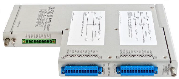
The 3500/32M and 3500/33 Relay Modules provide a set of relays that can be programmed to actuate based on alarm conditions in other monitor modules in the rack. The /32M module (left photo) uses double pole double throw (DPDT) relays, while the /33 module (right photo) uses single pole double throw (SPDT) relays. The /32M module has 4 DPDT relay channels and the /33 unit has 16 SPDT relay channels. The /33 can also be configured to act as if it has DPDT relays. Doing this will use two SPDT relays to perform the function of every DPDT relay that is configured. Although relay modules are not a required component of the 3500 System, we strongly recommend using them as the most appropriate way to integrate the 3500 System with automatic shutdown applications. Any number of relay modules can be placed in any of the slots to the right of the TDI 3500 System Configuration software facilitates programing “Alarm Drive Logic” that controls relay actuation. This logic can be based on various combinations of alarms, ranging from an individual channel’s Alert, Danger, or NOT OK status to highly complex Boolean expressions that combine two or more channel statuses to provide special AND or OR voting.
By adding the required number of relay modules to the rack, it is possible to provide individual relay contacts for each channel, alarm type, and group of channels for global alarm annunciation. The 3500 Rack supplies an overall Rack OK relay in addition to any alarm relays in the rack. The Rack OK relay is in the TDI’s I/O module and is connected to the OK circuits of all modules in the rack. These OK circuits monitor the operating condition of each module. Any fault in the module, its transducers, or associated transducer field wiring will be annunciated by the Rack OK relay. This relay is a single-pole, double-throw (SPDT) type and is normally energized, providing added capability of annunciation in the event of primary power loss. Note: Dozens of possible event conditions within the rack can drive the Rack OK relay to NOT OK status. For this reason, the Rack OK relay should not be used as part of a machinery auto-shutdown circuit, and should only be used for general annunciation purposes. Keyphasor Module
The 3500/25 is a half-height module that provides power and termination for up to two Keyphasor transducers. When applications require one or two Keyphasor transducers, simply install a single 3500/25 module. The 3500 System can accommodate up to four Keyphasor transducers per rack by installing two 3500/25 Keyphasor modules in the rack. Keyphasor signals from the 3500/25 module(s) can be routed to appropriate monitor modules via the 3500’s rack backplane for use in speed, phase, tracking filter, and other measurements. Communication Gateway
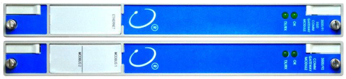
Communication Gateway modules allow a 3500 system to digitally transfer selected status and current value data to process control systems, historians, plant computers, and other relevant systems. The 3500/91 Ethernet Global Data (EGD) Comm Gateway Module accommodates integration with EGD compatible control systems, such as the GE Mark VIe. The 3500/92 Comm Gateway Module supports Modbus® communication, via serial and Ethernet protocols. Multiple communication gateway modules can be installed in a rack when the system requires redundant communication or must support multiple communication protocols simultaneously. The modules do not interfere with the 3500 System’s normal operations or machinery protection functions, ensuring that the monitoring system integrity is always maintained, even in the unlikely event of a Communication Gateway module failure.
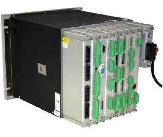
Input/Output (I/O) Modules Every module (Monitor, Keyphasor, Power Supply, Communication Processor, etc.) requires a corresponding I/O module. Main modules connect to the backplane inside the rack, and I/O modules connect with the other side of the backplane, behind their associated main modules. For bulkhead-mounted racks, only, each I/O module connects to the face of the backplane above its associated main module.
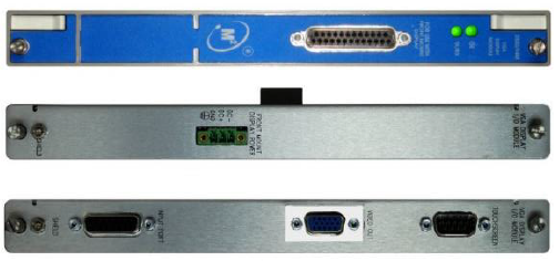
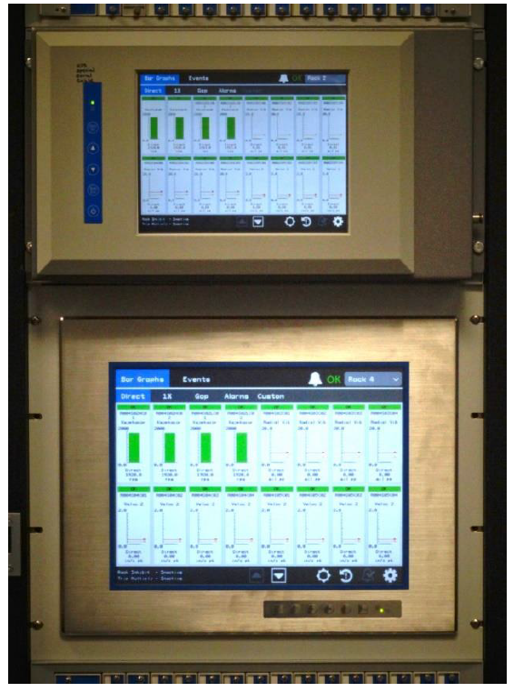
Touch Screen Display The 3500/94M VGA Display system provides a variety of flexible options, including both a 10” and 15” (diagonal) Touch Screen display
In addition to the 3500/94M VGA Display Module (left), the display package includes two I/O module choices. The power-only I/O module (middle) is for the 10” Face Mount display, while the standard I/O module (right) is for all other display options.
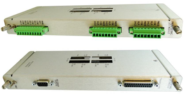
10” Display Face Mount option (upper), 15” Display 19” EIA Rack Mount option (lower) Intrinsic Safety Barriers or Galvanic Isolators For applications where the transducers are installed in a hazardous area, the 3500 System can be used with internal or external intrinsic safety barriers. Internal safety barriers are generally preferred to external barriers because this option saves cost, requires no extra cabinet space, and needs no additional wiring. Internal barriers also improve safety because the connections are pre-wired, reducing the possibility for errors introduced by wiring external connections between monitors and barriers. Internal barriers also improve quality because, unlike external barriers, they require no special monitor scale factor calibration to compensate for voltage drop across the barrier. For additional information, refer to the 3500 Internal Barriers Datasheet, 141495-01. If galvanic isolators are required to address your specific intrinsic safety requirements, pre-engineered external galvanic isolators and an appropriate housing are available. For additional information, refer to the 3500 Galvanic Isolator Interface Datasheet, 141714-01. Note: Due to the additional circuitry, internal barrier I/O modules add 74 mm (3 in) to the rack depth. Actual dimensions of all rack types can be found in the 3500 Monitoring System Rack Installation and Maintenance Manual, document number 129766.
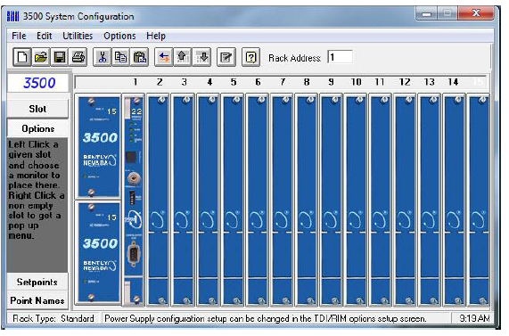
Prox/Seismic Internal Barrier I/O Module 3500 System Configuration Software This Windows®-based application is used to establish settings for all components of the 3500 Machinery Protection System. These settings are saved in the TDI in a proprietary RAK configuration file.
3500 System Configuration Software can be run on a laptop computer, which is connected locally to the USB port on the face of the TDI, or on a remote computer, which is connected to the TDI via the plant network. Configuration settings include the following:
For more information, refer to the 3500 Software datasheet, 141527.
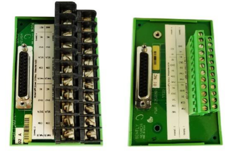
Internal and External Terminations Standard I/O modules accommodate field wiring connections directly to each I/O module. This is the traditional internal termination option. We also offer an External Termination (ET) option that allows field wiring to be landed at ET blocks. These ET blocks can be mounted where access is more convenient, such as on a cabinet wall, where the field wiring is less congested than when it connects directly to the back of each I/O module. Each ET block then connects to its monitor’s I/O module using a single pre-engineered cable with multipin connectors, resulting in neater, more easily serviceable installations.
I/O Modules for Internal Termination (left), and External Termination (right)
ET Blocks with screw terminals for lugged field wiring (left) and high-density “Euro” connectors for non-lugged field wiring (right) Features Overview The 3500 System is intended for continuous, permanent monitoring of rotating and reciprocating machinery in a variety of industries. It is specifically designed for use in auto-shutdown machinery protection applications that require extremely high reliability and availability. Applications Machine types addressed by the 3500 System include but are not limited to the following:
In addition, Bently Nevada Custom Products engineering can often address special requirements for custom configuration of an existing monitor type or modifications to a standard monitor type to accommodate monitoring of a unique machine. Contact your local sales professional for further information. Communications
Note: Although relays are not a required component of the 3500 System, we strongly recommended using them as the most appropriate way to interconnect the 3500 System in auto-shutdown applications. Analog (e.g. 4 to 20 mA) and digital (e.g. Modbus®) connections are intended for operator annunciation and trending purposes only and do not provide the fault tolerance or integrity necessary for highly reliable machinery shutdown purposes. Display Options Displays can range from local units mounted directly on the rack’s front panel, to remote displays, to completely blind monitoring systems with an as-needed HMI (Human Machine Interface) connection for configuration and information. Multiple displays can be connected concurrently without degrading system performance or interrupting basic machinery protection functions. See Graphs and Figures for more information on VGA Touch Screen display options. Monitor Configuration Virtually every aspect of the 3500’s operation is software configurable, which allows a smaller set of monitor types to perform a broader variety of functions. The list summarizes a few of the 3500 System’s configurable options.
Channel Density 4-channel Monitors allow a single full size (14 slot) 3500 rack to accommodate up to 56 monitoring channels. This efficient use of space results in lower installation costs by saving valuable cabinet space. It also facilitates sharing common components, such as displays, communications gateways, and power supplies, across more channels for less cost per channel. Reliability and Integrity The 3500 System can be configured with varying levels of redundancy. This ranges from simplex modules to dual power supplies to redundant relay modules with wide ranging and flexible logical operator options for configuring complex relay logic as needed. The 3500 System also offers a variety of Safety Integrity Level (SIL) certifications (SIL 1 and SIL 2) for various 3500 monitors used in safety instrumented systems subject to Functional Safety Certification. The 3500 System incorporates numerous self-monitoring functions that can identify faults in the monitor modules and their connected transducers, annunciate and identify problems via appropriate error codes, and suppress channel operation automatically when a failure could compromise correct operation of the system. The 3500 System stores configuration settings in two separate locations in each module’s non-volatile memory. This redundancy allows each module to compare configuration information for agreement and to flag any anomalies. The use of redundant, non-volatile memory also accommodates programming a spare module ahead of time. It also ensures that, in the event a redundant power supply is not used, monitor configuration is not lost when power is interrupted and monitoring functions can resume immediately upon reapplication of rack power. Refer to the Bently Manuals DVD for 3500 SIL Safety Manuals. Field Mounting In many cases, the 3500 rack can be mounted on or near the machine skid, foundation or local control panel, keeping cable runs between the 3500 rack and the monitored machine(s) shorter, less costly, and less prone to possible damage. The locally-installed rack can use a single Ethernet connection to communicate over the plant network. This allows it to distribute display data and other information to the control room, to a process control system or to a plant engineer’s desktop computer. The result is a machinery protection system with significantly lower installation costs than those that are limited to being mounted in control room environments. Optional NEMA 4 and NEMA 4X weatherproof housings are available when installations require field mounting of the 3500 System. Remote Accessibility Networked connections allow you to remotely configure a 3500 system and even assess the system when an instrument problem arises. You can implement simple changes, such as to an alarm setpoint or a filter corner, without traveling to the site in person. This is useful for installations at offshore platforms, compressor or pump stations, emergency generators, and other locations where on-site access to the instrumentation is inconvenient or impractical. Cybersecurity The 3500 System’s two levels of password protection combined with a keylock for configuration changes ensures the system can’t be adjusted, changed, or configured except by authorized personnel. The 3500 rack records any configuration changes in the system’s event list, which accommodates effective “management of change” documentation. We also offer Wurldtech™ Achilles® Level 1 certified solutions as well as full engineered and hardened network architectures when required to meet specific cybersecurity needs. Alarm/Event Lists Extensive alarm and event lists retain the 2000 most recent alarm events and 1000 most recent system events (configuration changes, errors, etc.). The system’s TDI retains the lists, which provide a description of each alarm or event and a corresponding date/time stamp. These lists are available to the 3500/94M VGA Display module and also to the Communication Gateway module for export to process control, historian, or other plant systems. Time Synchronization The system’s real-time clock can be synchronized with external clocks, via the Communication Gateway or via connected Bently Nevada software. The 3500 System’s alarm and event lists then provide time/date stamps that are synchronized with alarms and events in other process and automation equipment. This reduces or eliminates the need for elaborate, hardwired “Sequence of Event” recorders. API 670 Compliance When configured properly, supplied with the correct number of relay modules, and provided with an appropriate optional display, the 3500 System complies with the latest edition of the American Petroleum Institute (API) Standard 670 for Machinery Protection Systems, for shaft-relative vibration, axial position, temperature, reciprocating compressor rod drop, and casing vibration. Hot Insertion All Monitors and Power Supplies (when redundant supplies are used) can be removed or inserted when the rack is under power. This facilitates easier maintenance and system expansion without interruption of machinery protection functions or system operation. Note: Before removing an I/O module, the front-panel portion of the module must first be removed. This removes power from the slot so that the I/O module can then be safely removed without powering down the rack. I/O modules are NOT “hot-swappable.” System Mounting Options In addition to conventional 19” EIA rail and panel-cutout mounting options, the 3500 System includes a bulkhead mounting option, allowing the rack to be mounted on a wall or other location where rear access to the rack is not available. Enhanced Data Independent of System 1 Condition Monitoring and Diagnostics software, the 3500 System can provide multiple measurements from each transducer channel. For example, in addition to direct (unfiltered) vibration amplitude for a radial proximity probe channel, the 3500 monitor can return gap voltage, 1X amplitude and phase, 2X amplitude and phase, NOT 1X amplitude, and Smax amplitude (when XY transducers are present). Thus, a single radial vibration channel can return 8 conditioned parameters (measured variables) for a total of 32 in a single 4-channel monitor module. This is particularly valuable when machinery protection strategies require alarms on these measured variables. Activation or use of these values has no impact on rack density, and does not consume additional channels in the monitor. Note: ALERT alarm setpoints can be established on each proportional value, as desired. DANGER alarm setpoints can be established on any proportional values returned from each channel. Data Display Options The 3500 system can display data in a variety of ways, summarized below.
Graphs and Figures This graphical This graphical reference section includes additional information about the 3500 System. 3500 System Example
Working principle of Bently Nevada software including the installation click here If you have any more questions, give us a call, and our engineers will help.
www.bennypass.it
|
||||||||||||||||||||||||||||||||||||||||||||||||||||||||||||||||

.png)


+(39) 347 051 5328
Italy - Kazakhstan


09.00am to 18.00pm
About
We offer the best and economical solutions, backed by 27+ years of experience and international standards knowledge, echnological changes, and industrial systems.
Our Services
Marketing Materials


Marketing Materials1


