Linearity Check of Proximity Sensor
The vibration monitoring system is one of the most important systems for the protection of rotating machines like compressors, pumps, and turbines. The Bently Nevada 3500 (machinery protection system) is the most widely used system for the protection the rotating equipment. Many times, we face issues with vibration systems like vibration probe not responding, or vibration probe reading mismatch with consequence that machine will trip. For this reason the linearity of these sensors is very important, therebefore, the verification with special tool is mandatory.
NATURE OF ACTIVITY
- Linearity.
- Check for Radial and Axial vibration probes 3300 series
Procedure to verify the Linearity of Proximity Sensor
- Obtain work permit to perform the activity
- Explain to the person of responsible area that the work will be carried out by removing the probe from machine.
- Be sure that the stated compressor is stopped and safe to perform the linearity test. By-pass the ESD interlocks from sensors (if it is required during plant operation using deviation form).
- Remove the probe from machine
- Ensure that the probe is properly connected to its own extension cable (may be cable damage)
- The first step is to get the correct mounting hub for the specific probed diammeteryou are using
Field probe Verification and/or Calibration
Before starting this test, it’s required to check the two recommendations below
- If this test will be bench test, requires the power supply to the Proximity Transducer, if requires a field test, the Proximity Transducer should be already powered by monitor equipment. There is no difference between each other in term of functionality. For this article, we will use the field test (power supply already available)
- Before beginning the test you should determinate the linear range of the proximity equipment installed this one has a linear range of 80 mils starting at 10 mils and continuing out to 90. For check the linearity of sensor check the datasheet of it. Almost datasheet's you can find here
- Insert the probe till the tip contacts the face of the micrometer while it is adjusted to exactly zero thousandths of an inch, for more details see figure 2 below
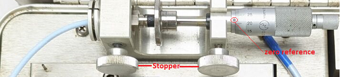
Figure 2 - Probe installed on the tool
- Lock it down and verify again that the mic stops at zero (stopper)
- As soon the probe will be install in the micrometer, connect the multimeter on the Proximity Transducer without remove the cable from controller (loop). If the face of sensor touch the face of the micrometer the multimeter must be read zero volt. for more details see figure 3 below
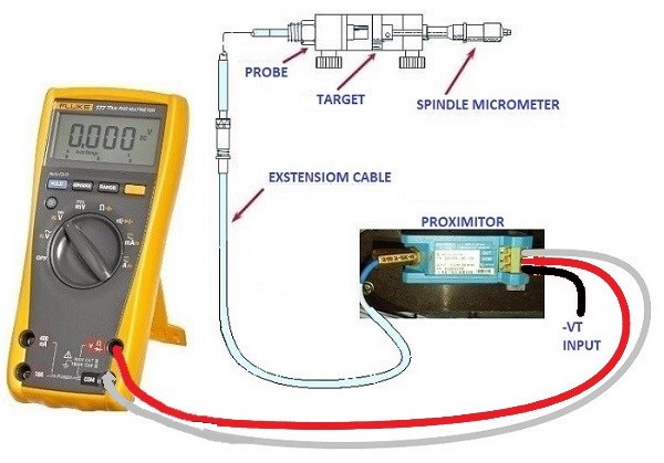
Figure 3 - Multimeter Connection
At the end of the test, you should have the sensor status and its linearity as demonstrated in Figure 4 below.
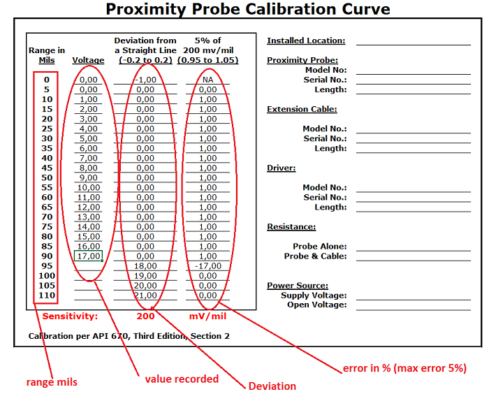
Figure 4 - Sensor linearity
Figure 4 above shows a new sensor without any deviation.
Figure 5 below shows an old sensor which requires to replace it because the deviation is more than 5%
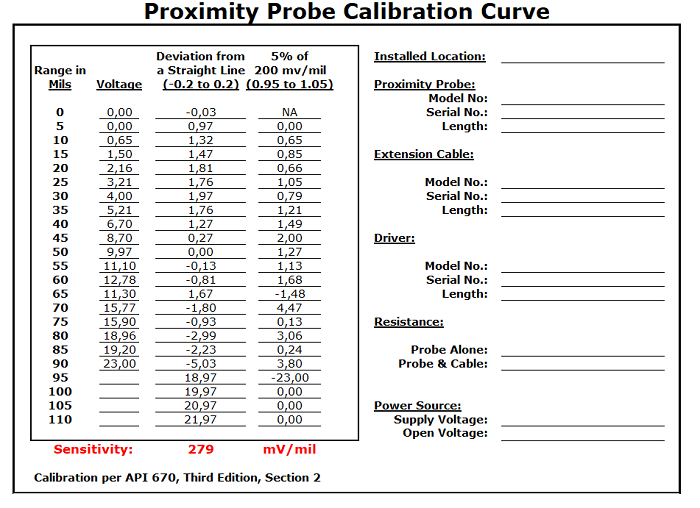
Figure 5 - Sensor Deviation
This type of calibration is one of the most important calibrations, but it is often overlooked because a lot of time is required.
The head of the vibration sensor is built inside with a coil to generate a radio frequency which will be read and converted into tension by the proximitor. The coil can change the value of the internal resistor at any time and can compromise the correct functioning of the measure or even on some points of measurement the sensor will read incorrectly. It should also be considered that a sensor that is not at 100% could send spikes and therefore trip machine or compressor for an emergency.
With this tool, you can define the sensor is 100% efficient or vice-versa, and therefore you can replace it without putting the machine at risk of stopping or shutdown (very important tools).
The excel file with automatic calculations and trend, you can find here
Vibration Probe Field Settings
- Measure the vibration proximitor drive voltage between common and V/T. It should be -24 VDC
- Measure the DC output voltage between common and output. It should be between -9.5 V and -10 VDC (as per the company this voltage standard will variable) if the output voltage is not between -9.5 V and -10 VDC then the vibration probe will need to be set.
- Remove the vibration probe cover and slacker off the probe lock nut with two spanners. One on the lock nut and the other on the probe adjustment nut adjust the probe depth until the reading on the voltmeter is between -9.5 and -10 Volts.
- If the probe adjustment does not affect the voltage reading try & different probe and if this does not work replace to vibration interface proximiter.
- If the fault is still present, move the CO-AX cable from both the proximiter and the vibration probe-measure resistance of the CO-AX cable by placing a short circuit between the cable centre conductor and the shield at line another end.
- The resistance should be approximately 0.8 ohms per meter length
Note: If the reading is below -9.5 V then the probe must be slacked (anticlockwise). If the voltage is above -10 V then the probe must be tightened (clockwise). When the correct voltage is obtained tightened the ballon lock nut. Refit vibration probe cover.
If a reading of zero or over 10 ohms is obtained then the cable is faulty and should be replaced.
| 0.2 V P/P |
70.7 mV ac |
25.44 micro ohm |
1 mil |
| 0.4 V P/P |
141.4 mV ac |
50.84 micro ohm |
2 mil |
| 0.6 V P/P |
212.7 mV ac |
76.2 micro ohm |
3 mil |
| 0.8 V P/P |
284 mV |
101.2 micro ohm |
4 mil |
| 1.0 V P/P |
353.5 mV |
127.4 micro ohm |
5 mil |
| 2.0 V P/P |
707 mV |
254 micro ohm |
10 mil |
Figure below shows the connection with the multimeter
Conclusion
- When installing a complete vibration sensor loop must be rigorously followed the type number of proximitor and apply the correct extension coaxial cable which is 5 or 9 0r 11 meters etc.
- The connection between sensor and proximitor must be rigorously perfect without any cable or pin connection damage.
- The proximity sensors must be checked with the calibration tools if they correspond to the real values (very important). Unfortunately, this type of work is not always performed because to calibrate the sensor should be remove it from the machine (a lot of time is required, especially when a lot of sensors are in place).
www.bennypass.it
|


