
|
Intrinsic Safety Isolators | Isolated Barriers for Hazardous
Introduction For an explosion, all three of gas/dust, oxygen and source of ignition (spark or heat) need to be present (triangle of the fire). Intrinsic Safety (IS) works on the principle of removing the source of ignition. This can be achieved by using a Zener barrier or galvanic isolator. The three principles of Ex i design are defined as follows:
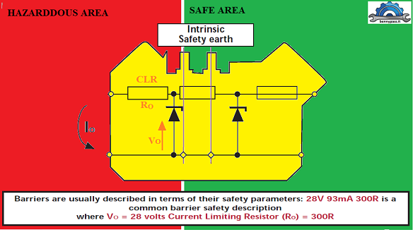
A Zener barrier is a simple device where the voltage and current (power, energy) is limited into the hazardous area. The voltage is limited (clamped) by a Zener diode and the current limited by an output resistor. The fuse is there to protect the Zener diode. The key to safety is the intrinsically safe (IS) earth. Without it, there is no protection. These components are all ‘Safety Components’ meaning components upon which safety depends. The Zener barrier is usually designed for zone 0 connectivity [Exia] and can then be used for zone 1 [Exib] and zone 2 [Exic]. For Exia, the Zener barrier has to be safe with two faults, so the safety components have to be assessed to ensure they cannot fail unsafe. This is achieved through the duplication of Zener diodes. Safety components also have a 1.5 safety factor which means that under fault conditions, they never dissipate more than 2/3 of their commercial rating.
Modes of operation When Zener barriers are used, they need to be considered in 2 modes: fault condition and operational.
In a current loop, leakage current through Zener diodes can affect accuracy. V working is defined as the maximum voltage at which leakage current is less than 10 μA. Vmax is defined as the maximum voltage that can be applied continuously at the input terminals such that the fuse will not blow.
Zener barrier A Zener barrier is a simple device where the voltage is limited by a Zener diode and the current by a resistor. A fuse is present to protect the Zener diode as shown in Figure 1. The key to safety is the intrinsically safe earth. Without it, there is no protection. If the input voltage increases above Zener diode voltage, the Zener conducts and the fuse blows, after which the Zener barrier needs to be replaced. In addition, the barrier has a volt drop across it under normal operating conditions, so careful calculation must be done to ensure that there is sufficient voltage at the field device. [Note: using Zener barriers without an IS earth is not safe.] Fig. 1 illustrates how a shunt diode safety barrier is constructed so as to limit the current and voltage available from the hazardous-area terminals. The fuse restricts the fault power, the zeners restrict the voltage and the current limiting resistor [CLR] restricts the curren Fig 1 Shunt diode safety barrier
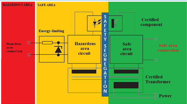
The galvanic isolator illustrated in Fig. 2 breaks any direct connection between safe- and hazardous-area circuits by interposing a layer of insulation between the two. The power transfer is usually via some form of transformer and the return signal via an optocoupler, transformer, or relay. The final power limitation is achieved by using a diode resistor network very similar to that of a shunt-diode barrier.
Fig.2 Galvanic Isolation
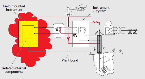
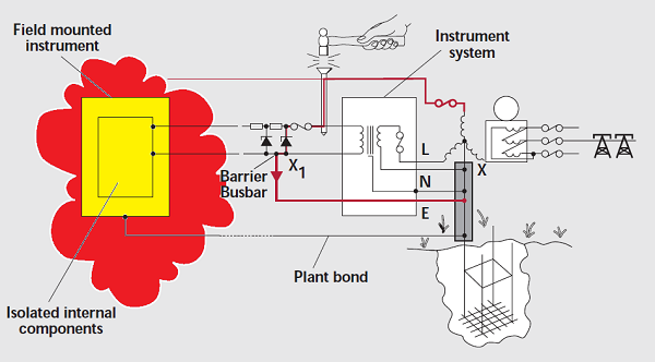
Figures 5 and 6 Since the hazardous-area circuit from an isolator is not directly connected to the safe area circuit, it is usual to regard the fundamental action as effectively blocking the excessive energy at the layer of insulation. In practice, the 0V of the instrument system is normally returned to the neutral star point for interference avoidance and safety reasons. The resultant fault current is thus returned to the neutral star point in the usual way, rupturing the protective fuse and removing the fault, in a relatively short time.
The conventional fault consideration of the shunt-diode barrier is illustrated in Fig 6 where the fault current is returned to the neutral star point within the safe area in much the same way. The important difference is that the transient voltage difference between the barrier busbar and the neutral star point [X1 X] is now transferred to the hazardous area and hence must be restrained to a low level [less than 10V]. In consequence, the busbar to neutral star point bond on the shunt diode safety barrier must be of low resistance and be secure, since it is critical to safety.
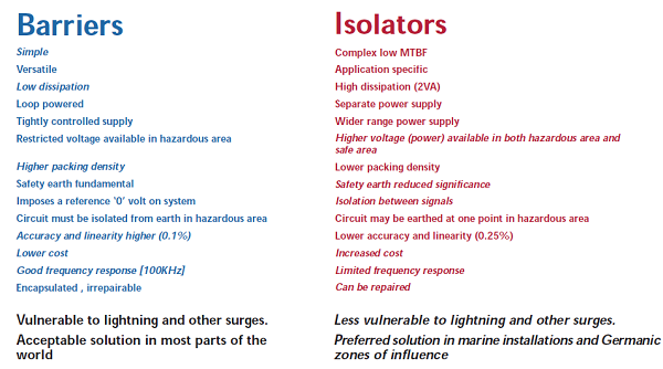
Figure 7 show the lists of relative merits of isolators and barriers and the significance of these factors varies with the particular installation. The remainder of the document expands these points of comparison so that they can each be evaluated.
Figure 7. Comparisons
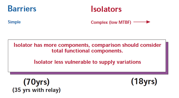
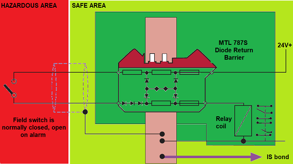
Figures 8, 9 and 10 show in general the lower number of components and basic simplicity of the shunt-diode safety barrier means they are considered to be more reliable. A more accurate comparison has to compare the reliability of an isolator with the barrier plus additional components required to accomplish the same function. For example, Figs 9 and 10 show the usual switch contact transfer using a barrier relay combination which should be compared with the more complete functions of the isolator. This reduces the apparent superiority of the barrier.
Figure 8 Comparisons
Figure 9 Switch with Zener Barrier: preferred solution
|

+(39) 347 051 5328
Italy - Kazakhstan


09.00am to 18.00pm
About
We offer the best and economical solutions, backed by 27+ years of experience and international standards knowledge, echnological changes, and industrial systems.
Our Services
Marketing Materials


Marketing Materials1


