
Nickel-Cadmium and Nickel-Metal Hydride battery charger
Introduction
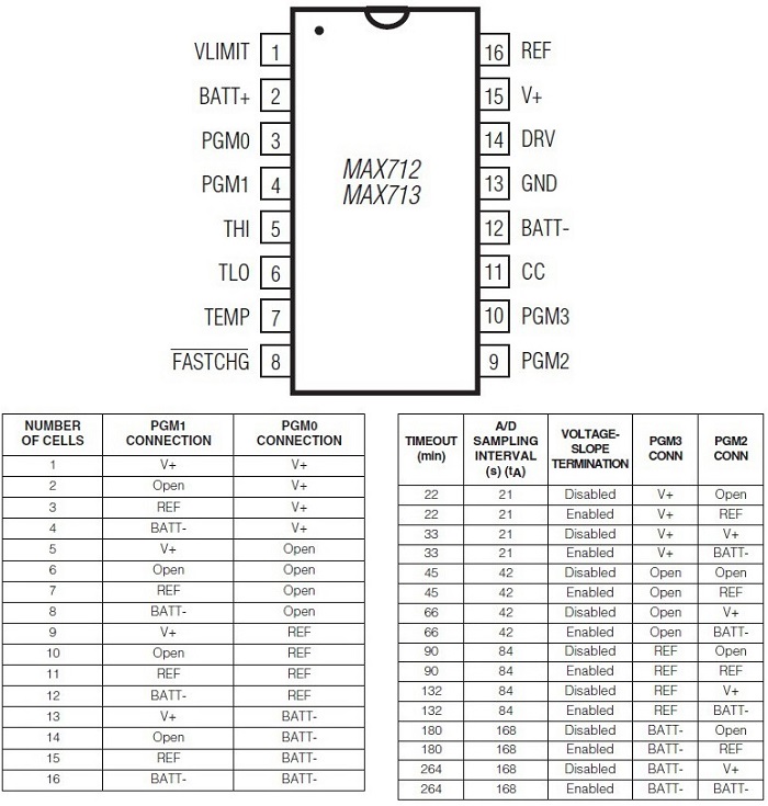
The integrated MAX712 is used to load nickel-cadmium and nickel-metal hydride batteries from a DC source. It allows you to load batteries in series from a minimum of one battery to a maximum of 16 with the possibility of fast charging at a rate higher than 4C or with a current of 4 times the capacity of the batteries. To determine the maximum charge it uses a voltage detection across the series of batteries (detects the slope of the voltage over time) and also uses a temperature control. The MAX712 provides a minimum current of 5uA even when the batteries are charged, in such a way that they remain always charged, thus compensating for self-discharge. It allows to have a load connected to the batteries even during their charge. To check the number of batteries on charge including the charging time, we have 4 control pins that are used as per photos below:
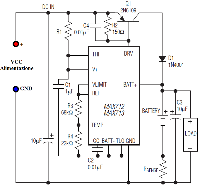
PGM0 and PGM1 are used to check the number of batteries being charged, for example: If there are two batteries the PGM0 is connected to the V + pin and PGM1 is not connected. PGM3 and PGM2 control the charging time and the method to determining the end of charge and the charging current, the fast charge, including the normal charging. Suppose we want to load in fast charge with a current equal to the capacity of the batteries, for example: We charge 2200mAh of the batteries, so the fast charge uses a current of 2.2A. PGM3 connects to the REF pin that is pin 16, while, PGM2 is connected in such a way that controls the slope of the voltage across the battery with a charging time of 90 minutes, then it connects to the pin REF which is also the pin 16. To control the charging current we have a sensing resistance that has a specific value Typical drawing without temperature control is as follows:
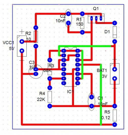
As supposed in the previous case, pin 3 (PGM0) is connected to pin 3 (V +), while pins 9 and 10 (PGM2, PGM3) is connected to pin 16 (REF), this considering a charge current equal to C, a time of 90 minutes, and a number of batteries equal to two. For example:
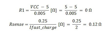
The Resistance R1 is not necessary while the sensing resistance must have a value of 0.12 Ohm (120 mOhm) to have a charge current of 2A. Inside the scheme is not used the pin 8 or FASTCHG, this pin is at low level during the fast charge, so if we connect a cathode of a led to this pin and we connect the anode to VCC through a protective resistor, the LED will be turned on during the fast charge phase. Q1 and R2 are used to generate the charging current, R1 protects the MAX712, R3 and R4 simulate the temperature sensor and D1 means that there are no output currents from the batteries towards the input voltage. The input voltage can be generated by a voltage transformer, Diode Bridge, and filtering capacitor or a DC / DC converter. The diagram printed on the printed circuit board is as follows:
For more details read the manual here
www.bennypass.it |

+(39) 347 051 5328
Italy - Kazakhstan


09.00am to 18.00pm
About
We offer the best and economical solutions, backed by 27+ years of experience and international standards knowledge, echnological changes, and industrial systems.
Our Services
Marketing Materials


Marketing Materials1


