
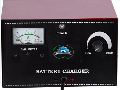
Battery Charger for Lead Batteries
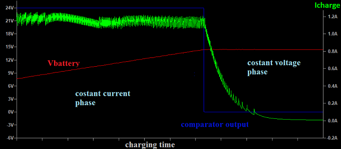
Introduction The following diagram uses an MC34063 to realize the control element of the switching circuit, and thanks to an operational one realize the voltage and current control in such a way as to charge the battery with a first constant current phase and then a second voltage phase constant. Analyzing the current battery voltage graph, which is thanks to this graphic you will have the following situation:
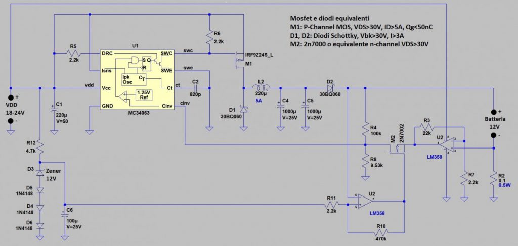
The current is constant in the first phase when the output comparator is at a value of 24V, while the battery voltage increases linearly. This graphic is the result of a simulation since it is not possible to capture a graphic for the entire charging time. In reality, the current has a much smaller ripple and therefore can be considered constant. When the comparator output goes to 0V level, the control warns the integrated circuit that controls the switching regulator that must switch from constant current to constant voltage and the current consequently decreases exponentially. When the comparator output goes to 0V level, the control warns the integrated circuit that controls the switching regulator that must switch from constant current to constant voltage and the current consequently decreases exponentially. Thanks to this control the lead-acid battery receives a charge suitable for its chemistry and therefore will have a longer life. The whole control and switching circuit absorb the power of about 4W, while the charge can also be made at 50W, so efficiency of about 92%. The figure below shows the drawing:
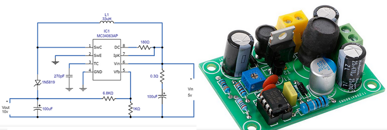
Figure below show the module MC34063AP
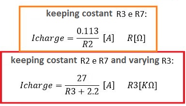
The switching type regulator is made by an MC34063 and in particular, C2 is used to dictate the integrated clock frequency while R5 is used to drive the internal switching element. For a higher charge current, a p-channel MOSFET is used as a switch element. The switching regulator is concluded with D1, a Schottky diode with a voltage greater than 30V and a current greater than 3A, a 220uH inductor and current supported by 5A, and two capacitors (C4 and C5) in parallel so as to reduce the ripple of the tension to their leaders. The MC34063 integrated controls the MOSFET in such a way that there is a voltage of 1.25V on the Cinv feedback pin. the feedback voltage is generated in two different ways. If it is in the first phase with constant current, the feedback voltage is given by the voltage across the amplified sensing resistance R2 of a value 11. If in the phase with constant voltage, the feedback voltage is generated by R4 and R8. We start from the first phase; the switching regulator generates a voltage such as to make a constant current flow because the control is done in current. The value of the current is the value of the charging current and can be adjusted in two ways, as per the photo below:
Where in the first formula the resistance is expressed in Ω whereas in the second formula it is expressed in KΩ. Considering the values of the proposed circuit, the charging current is equal to 1.15A. All that remains is to go to select one of the two feedbacks, to do this we use a Schmitt trigger comparator and an n-channel type MOSFET. The comparator receives a reference voltage of about 14.1V thanks to the Zener diode and the three diodes, when the battery voltage is around the reference voltage value then the comparator changes its output from high to low. If the output voltage of the comparator is at 24V then M2 is on and the feedback is given by the current, otherwise, the M2 is off and the feedback is given by the voltage.
www.bennypass.it |

+(39) 347 051 5328
Italy - Kazakhstan


09.00am to 18.00pm
About
We offer the best and economical solutions, backed by 27+ years of experience and international standards knowledge, echnological changes, and industrial systems.
Our Services
Marketing Materials


Marketing Materials1


