
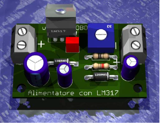
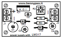
Variable power supply with LM317
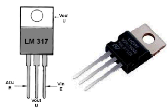
The integrated LM317 It is the circuit integrated which has dimensions identical to those of a normal transistor of average power type TO.220, they have only three feet (see Figure 1).
Figure 1
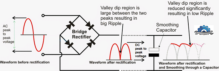
The pin E or VIN as indicated in figure 1 receives the positive voltage to be stabilized which is withdrawn from a rectifier bridge where is included an electrolytic capacitor for removing any AC (ripple). See figure 1a below
The pin R or ADJ as indicated in figure 1 is the adjustment foot, which is used to vary the output voltage to the desired value. The pin U or VOUT as indicated in figure 1 is the one where stabilized voltage is taken.
Figure 2
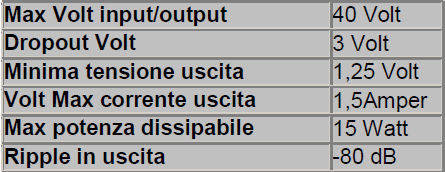
Max Volt input/output: Many people believe that this value indicates the maximum applicable voltage on the entrance to the LM 317. This is not true, this integrated accepts on the input also voltages of 60 - 80 - 100 Volt, important is the difference between the voltage applied to the input and the one taken at the outlet should not be than 40 Volt. To explain better what is meant by this difference, we will give you some examples:
Drop out Volts: Figure 2 indicates the voltage drop introduced by the LM 317. So if you apply a voltage of 46 Volts on the input, the maximum stabilized voltage that you can withdraw on the output will never exceed:
The minimum voltage of the output: The value of 1.25 Volt indicates the minimum stabilized voltage that is possible to withdraw from the LM 317 (as per datasheet). Max current of output: The maximum current that LM.317 is able to deliver is 1.5 Ampere, but with a cooling fan. Without a cooling fan, the maximum current is below 0.5 or 0.7 Ampere. Max power: The power of 15 Watt reported in the characteristics is obtained only if the body of the LM 317 is fixed above a cooling fin. If the cooling fans fail to dissipate the heat generated and exceeds the temperature of the safety limit, the thermal protection will activate. The LM 317 lowers the output voltage, which therefore will no longer be stabilized, and it overheats considerably. Output ripple: For those who do not know, the ripple is the residual AC voltage that is found on the continuous voltage stabilized. As in this case, we talk about a ripple equal to -80 dB, it means that the alternating residual present on the stabilized DC voltage is less than 10,000 times. Therefore, if you have adjusted the power supply for an output voltage of 18 volts, this may result in an alternating residue of 0.0018 Volts equal to a value that is negligible. Below components characteristics:
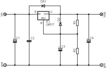
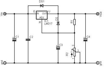
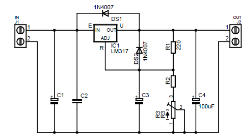
Figure 3
Calculation of the R2 Knowing the voltage value, to calculate the R2 resistance value you will have to use this simple formula: R2 ohm = [(Volt output: 1.25) - 1] x 220 Volt output: indicate the value of voltage that is to be taken at the output of LM317. Number 1.25: indicate the difference in voltage that exists between the output and the adjustment feet. Number 1: is a fixed number supplied by the Manufacturer. Number 220: is the value in ohms of the resistance R1 applied to the resistive divider. The figure below shows the full drawing
www.bennypass.it |

+(39) 347 051 5328
Italy - Kazakhstan


09.00am to 18.00pm
About
We offer the best and economical solutions, backed by 27+ years of experience and international standards knowledge, echnological changes, and industrial systems.
Our Services
Marketing Materials


Marketing Materials1


